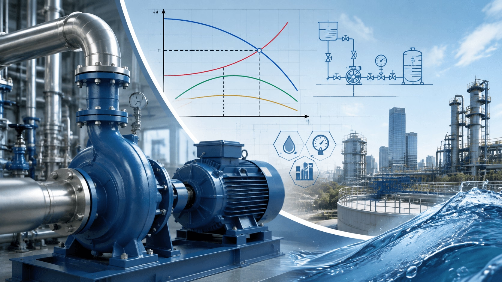
A practical engineering guide to pump selection, explaining how to match flow rate, total dynamic head, NPSH, efficiency, and pump type to system requirements. Step-by-step methodology for proper pump sizing and lifecycle efficiency from Techo Electrical & Mechanical (Titecho).
1. Introduction
Pump selection represents one of the most consequential yet frequently misunderstood tasks in fluid system design. An incorrectly sized pump wastes energy, suffers premature mechanical failure, and fails to deliver the required process performance. Conversely, a properly selected pump operates quietly near its Best Efficiency Point (BEP), consumes minimum energy, and achieves its design lifespan of 15–25 years.
This guide distils the essential engineering principles of pump selection into a practical, step-by-step methodology that connects system requirements to pump specifications through the fundamental parameters of flow rate, total dynamic head, and efficiency.
2. Define the System Requirements
2.1 Flow Rate (Q)
Flow rate is the volume of fluid the pump must move per unit time. It is determined by the process demand, not by pump capability.
| Application | Typical Flow Determination | Common Units |
|---|---|---|
| Water supply | Peak daily demand + fire flow | m³/h, L/s, GPM |
| HVAC circulation | Heat transfer requirement | m³/h, GPM |
| Irrigation | Crop water requirement × area | m³/h, L/s |
| Chemical process | Batch cycle time or continuous production | m³/h, L/min |
| Drainage/sump | Inflow rate from rainfall or leakage | L/s, GPM |
Engineering Rule: Size for the maximum sustained flow the system will experience, not the absolute peak. Transient peaks can be accommodated through storage capacity, multiple pump configurations, or variable-speed control.
2.2 Total Dynamic Head (TDH)
TDH represents the total energy the pump must impart to the fluid, expressed as the equivalent height of the fluid column:
TDH = H_static + H_friction + H_pressure + H_velocity
| Component | Description | Calculation Method |
|---|---|---|
| Static head | Elevation difference between suction and discharge | Direct site measurement |
| Friction head | Losses in pipe, valves, fittings & equipment | Darcy-Weisbach / Hazen-Williams |
| Pressure head | Pressure differential between vessels | ΔP / (ρ × g) |
| Velocity head | Kinetic energy difference (usually negligible) | (v₂² - v₁²) / (2 × g) |
Typical Design Velocities:
- Suction piping: 1.0–2.0 m/s (3–6 ft/s)
- Discharge piping: 1.5–3.0 m/s (5–10 ft/s)
3. Understand the Pump Curve
3.1 The Head-Flow (H-Q) Relationship
A centrifugal pump's H-Q curve illustrates how head capacity decreases as flow increases:
| Curve Shape | Impeller Type | Characteristics |
|---|---|---|
| Flat | Low specific speed, radial flow | Small head change with large flow variation |
| Steep | High specific speed, axial flow | Large head change with flow; suitable for pressure control |
| Drooping | Poorly designed or worn impeller | Unstable operation; multiple possible flow points |
3.2 Power and Efficiency Curves
| Curve | Description | Selection Implication |
|---|---|---|
| Power-Flow (P-Q) | Brake horsepower versus flow rate | Size motor for maximum power point on the curve |
| Efficiency-Flow (η-Q) | Hydraulic efficiency versus flow rate | Operate within 80–110% of BEP for optimal performance |
Best Efficiency Point (BEP) is the flow rate at which pump efficiency is maximised. Operating far from BEP causes internal recirculation, overheating, cavitation, excessive vibration, and potential motor overload.
4. System Curve and Operating Point
4.1 Constructing the System Curve
The system curve plots TDH versus flow rate for the specific piping network:
H_system = H_static + k × Q²
| System Type | Characteristic | Example |
|---|---|---|
| Static head dominated | Flat curve; elevation loss dominant | Well to elevated tank water supply |
| Friction head dominated | Steep curve; friction rises rapidly with flow | Long pipelines, closed-loop HVAC systems |
| Combined | Moderate curve; balanced static and friction losses | Most industrial process systems |
4.2 Operating Point Determination
The actual operating point is the intersection of the pump H-Q curve and the system curve. Both oversized and undersized pumps create long-term reliability and energy consumption issues. Variable-speed control represents the most efficient method to dynamically match pump output to varying system demand.
5. NPSH: The Critical Suction Constraint
5.1 NPSH Available vs. NPSH Required
NPSH Available (NPSHa) depends on the installation configuration and fluid properties. NPSH Required (NPSHr) is defined by pump manufacturer testing under controlled conditions.
NPSHa = (P_surface - P_vapour) / (ρ × g) + H_static,suction - H_friction,suction
5.2 The NPSH Safety Margin
| Application | Recommended Margin |
|---|---|
| General water pumping | 0.5–1.0 m (1.5–3 ft) |
| High-temperature / volatile liquids | 1.5–3.0 m (5–10 ft) |
| Suction lift conditions | 1.0–1.5 m minimum |
| High-energy pumps (> 100 kW) | 1.5 m or 1.3 × NPSHr |
6. Pump Type Selection
6.1 Specific Speed as the Selection Guide
| Specific Speed Range | Pump Type | Head-Flow Characteristic | Typical Efficiency |
|---|---|---|---|
| 500–1,000 | Radial (single-stage) | High head, low flow | 50–75% |
| 1,000–4,000 | Mixed flow | Medium head, medium flow | 70–85% |
| 4,000–9,000 | Axial flow (propeller) | Low head, high flow | 75–90% |
| 1,000–5,000 | Multi-stage radial | Very high head, moderate flow | 65–85% |
6.2 Application-Specific Pump Selection
| Application | Typical Duty | Recommended Pump Type |
|---|---|---|
| Boiler feed | High pressure, high temperature | Horizontal multi-stage |
| Cooling water | Medium flow, low-medium head | Split-case / axial flow |
| Sewage/wastewater | Solids handling, moderate head | Non-clog submersible |
| Building pressure boost | Variable flow, constant pressure | Vertical multi-stage inline + VFD |
7. Efficiency Optimisation and Energy Considerations
7.1 Control Method Comparison
| Control Method | Relative Energy Consumption | Application Suitability |
|---|---|---|
| Throttling (valve) | 100% (baseline waste) | Avoid for continuous duty |
| Bypass recirculation | > 100% (worst case) | Emergency operation only |
| Multiple pump staging | 60–80% | Variable demand systems |
| Variable Frequency Drive (VFD) | 30–60% | Best for variable-flow systems |
7.2 Lifecycle Cost Distribution
| Cost Component | Typical Share | Optimisation Focus |
|---|---|---|
| Energy | 85–90% | BEP operation, VFD integration, high-efficiency motors |
| Maintenance | 5–10% | Seal protection, bearing condition monitoring |
| Initial capital | 3–5% | Avoid oversizing; right-size for duty |
8. Motor Sizing and Specification
8.1 Service Factor Guidance
| Application | Recommended Service Factor |
|---|---|
| Clean water, steady load | 1.10–1.15 |
| Wastewater, moderate solids | 1.15 |
| Abrasive slurry, heavy duty | 1.20–1.25 |
8.2 Speed Selection
| Speed (50 Hz) | Best Application | Considerations |
|---|---|---|
| 2-pole (3000 rpm) | High head, compact design | Higher NPSHr & acoustic noise |
| 4-pole (1500 rpm) | General-purpose balanced performance | Most common industrial standard |
| 6-pole (1000 rpm) | Low head, high flow, low NPSH | Larger frame size required |
9. Common Selection Errors and Prevention
| Error | Consequence | Prevention |
|---|---|---|
| Oversizing for future expansion | Low efficiency, internal recirculation, short service life | Size for current duty + VFD flexibility |
| Ignoring NPSH margin | Cavitation, impeller pitting, seal failure | Calculate NPSHa with adequate safety margin |
| Wrong viscosity correction | Reduced head, flow, and efficiency | Apply HI standard viscosity corrections |
| Selecting based on price alone | High lifecycle cost, frequent failures | Evaluate TCO over 10–15 year horizon |
10. Specification Checklist
Before finalising a pump procurement, verify the following:
- Flow rate: Maximum, minimum, and normal operating flows defined
- TDH: Calculated at all flow conditions including future system changes
- NPSH: Available NPSH calculated and verified > required NPSH + safety margin
- Fluid properties: Density, viscosity, temperature, solids content, chemical composition documented
- Pump type: Matched to specific speed and application requirements
- Efficiency: BEP located near expected operating range; high-efficiency motor specified
- Control strategy: VFD, throttling, or pump staging selected for duty cycle
- Wetted materials: Fully compatible with pumped fluid and ambient environment
- Motor specification: IE3/IE4 efficiency class; correct service factor; VFD-rated if applicable
11. Conclusion
Proper pump selection is fundamentally an exercise in system engineering, not merely catalog selection. The pump must be matched to the system curve, not the other way around. Success requires accurate flow definition, precise TDH calculation, strict NPSH verification, and correct pump type selection based on specific speed.
The most costly pump failures stem from oversizing, off-BEP operation, cavitation, and neglected lifecycle costs. Following this structured selection methodology ensures long-term reliability, minimal energy consumption, and full compliance with global industrial pumping standards including ANSI/HI, IEC 60034-30-1, and DOE regulations.
12. Engineered Pump Solutions with Titecho
Techo Electrical & Mechanical (Taizhou) Co., Ltd. (Brand: Titecho) specialises in high-efficiency pump systems and the precision electric motors that drive them. Our product portfolio encompasses centrifugal pumps, multi-stage systems, and IE3/IE4 high-efficiency motors engineered for demanding industrial, HVAC, and water treatment applications.
We provide comprehensive engineering support, including system curve analysis, NPSH verification, pump-motor matching, VFD integration guidance, and total cost of ownership analysis to ensure optimal system performance.
Explore technical data sheets, performance curves, and application engineering support at www.cntecho.com.
© Techo Electrical & Mechanical (Titecho) – Precision Fluid Handling for Industrial Excellence