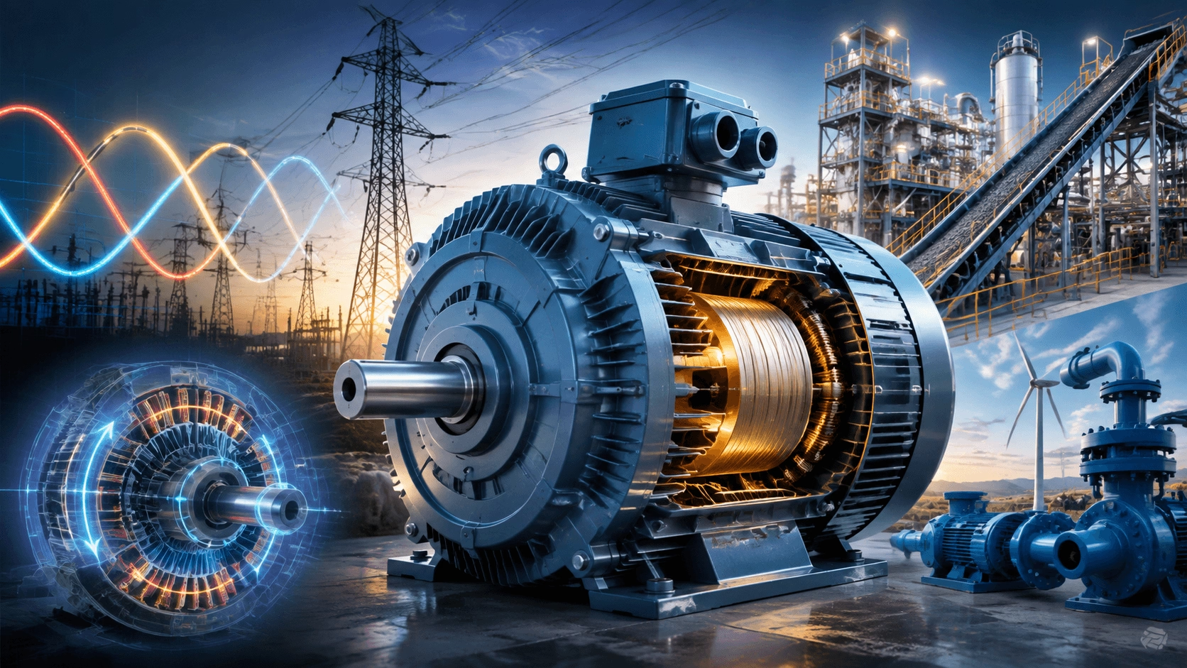
A comprehensive technical analysis of the efficiency, reliability, power density, and lifecycle cost advantages that establish three-phase motors as the undisputed standard in industrial applications. Expert engineering insights from Techo Electrical & Mechanical (Titecho).
1. Introduction
Three-phase AC motors have constituted the cornerstone of industrial electrification for over a century, powering critical infrastructure ranging from conveyor networks and pumping stations to massive steel rolling mills and wind turbine generators. While single-phase and DC motors serve specific niche applications, three-phase systems account for the overwhelming majority of industrial motor installations globally.
This market dominance is not accidental; it is the direct result of fundamental electrical engineering principles that confer decisive advantages in efficiency, reliability, power density, and total cost of ownership (TCO). This guide examines the technical and economic rationales underpinning the supremacy of three-phase motors in modern industrial power systems.
2. Fundamental Principles: The Physics of Three-Phase Power
2.1 The Rotating Magnetic Field (RMF)
The defining electromagnetic advantage of three-phase power lies in its inherent ability to produce a smooth, self-starting rotating magnetic field (RMF) without the necessity for external switching mechanisms or auxiliary windings.
In a three-phase stator with windings spatially displaced by 120 electrical degrees, the balanced sinusoidal currents are defined as:
i_a = I_m × sin(ωt)
i_b = I_m × sin(ωt - 120°)
i_c = I_m × sin(ωt - 240°)
These currents generate a resultant magnetic field vector that rotates at a constant synchronous angular velocity:
ω_sync = 2πf / p
Where:
- f = Supply frequency (Hz)
- p = Number of pole pairs
Key Insight: Unlike single-phase systems, which produce a pulsating (non-rotating) field requiring auxiliary starting mechanisms, the three-phase RMF is inherently balanced and self-starting. This eliminates the need for centrifugal switches, start capacitors, or shaded poles—components that inherently increase cost, reduce reliability, and limit operational performance.
2.2 Constant Instantaneous Power
A critically important, yet frequently overlooked, advantage is that balanced three-phase systems deliver constant instantaneous power:
P_3φ = √3 × V_L × I_L × cos(φ)
Conversely, single-phase power pulsates at twice the supply frequency:
P_1φ(t) = V × I × cos(φ) × [1 - cos(2ωt)]
The absence of a time-varying power component in three-phase systems yields profound mechanical benefits:
- Zero Torque Pulsation: The motor develops smooth, continuous torque, eliminating the oscillating torque that induces vibration and mechanical stress.
- Uniform Mechanical Output: Reduces cyclic fatigue on bearings, couplings, and driven equipment.
- Optimal Magnetic Utilisation: The stator core does not experience cyclic saturation variations, reducing acoustic noise and core losses.
3. Efficiency and Conductor Economics
3.1 Copper Utilisation and Conductor Economics
Three-phase systems are fundamentally more efficient in their utilisation of conductive materials. For the transmission of equivalent power:
| Parameter | Single-Phase System | Three-Phase System |
|---|---|---|
| Conductors Required | 2 (Line + Neutral) | 3 (No neutral required for balanced loads) |
| Copper Mass (Same Power & Voltage Drop) | ~1.5× Baseline | Baseline (1.0×) |
| Power Transmitted per Conductor | P / 2 | P / 3 |
| Conductor Utilisation Efficiency | Lower | Higher |
The relationship between conductor cross-section and power transmission is governed by:
I_L = P / (√3 × V_L × cos(φ))
Compared to single-phase current (I_1φ = P / (V × cos(φ))), a three-phase system requires approximately 25% less total copper mass for the same power transmission and equivalent voltage drop, assuming balanced loading.
3.2 Motor Efficiency Comparison
Modern three-phase induction motors routinely achieve premium efficiency levels (IE3/IE4 per IEC 60034-30-1, or NEMA Premium®):
| Power Rating | Typical Single-Phase Efficiency | Typical Three-Phase Efficiency |
|---|---|---|
| 1 kW | 75–82% | 84–87% |
| 5 kW | N/A (Rarely manufactured) | 89–92% |
| 50 kW | N/A | 93–96% |
| 500 kW | N/A | 95–97% |
The efficiency gap arises from the elimination of auxiliary windings, the absence of loss-dissipating starting components, optimal winding distribution to minimise harmonic content, and superior thermal management facilitated by symmetrical construction.
3.3 Power Factor Considerations
Three-phase motors inherently operate at significantly higher power factors:
- Three-phase induction motors: 0.80–0.90 lagging at full load (up to 0.95 for premium designs).
- Single-phase motors: 0.55–0.75 lagging, with substantial variation across the load profile.
A higher power factor directly reduces reactive power draw (Q = P × tan(φ)) and apparent power (S = √(P² + Q²)), resulting in smaller infrastructure requirements and the avoidance of utility penalty tariffs.
4. Reliability and Mechanical Robustness
4.1 Elimination of Starting Components
Single-phase motors rely on auxiliary starting mechanisms that represent primary failure points:
| Component | Primary Failure Mode | Operational Impact |
|---|---|---|
| Start Capacitor | Electrolyte desiccation, dielectric breakdown | Loss of starting torque |
| Centrifugal Switch | Contact welding, mechanical wear | Failure to start or failure to transition to run winding |
| Run Capacitor | Capacitance drift over time | Reduced performance, thermal runaway |
| Starting Winding | Thermal degradation of insulation | Intermittent starting failure |
Three-phase motors eliminate these components entirely. The rotor initiates rotation automatically upon energisation, leaving bearings as the primary wearing parts, thereby dramatically improving Mean Time Between Failures (MTBF).
4.2 Symmetrical Construction and Bearing Life
The 120° spatial symmetry of three-phase windings ensures balanced radial magnetic forces, uniform thermal distribution, and predictable thermal expansion. In contrast, single-phase motors experience pulsating radial forces at twice the line frequency, accelerating bearing fatigue.
Bearing life is governed by the ISO 281 relationship:
L_10 = (C / P)^p × [10^6 / (60 × n)]
Where:
- C = Dynamic load rating
- P = Equivalent dynamic load
- p = Life exponent (3 for ball bearings)
- n = Rotational speed (rpm)
The smooth, non-pulsating torque profile of three-phase motors results in a lower effective dynamic load (P), extending bearing life by 30–50% compared to single-phase motors of equivalent power rating.
5. Power Density and Scalability
5.1 Physical Size Comparison
For a given power output, three-phase motors are significantly more compact due to higher specific electric loading, superior cooling surface-to-volume ratios, and the absence of "dead" space allocated to starting components.
| Power Rating | Single-Phase Frame (Approx.) | Three-Phase Frame (Approx.) | Size Reduction |
|---|---|---|---|
| 1 kW | 280 mm | 90 mm | ~68% |
| 5 kW | Rarely available | 112 mm | — |
| 50 kW | Not manufactured | 225 mm | — |
| 500 kW | Not manufactured | 355 mm | — |
5.2 Scalability to High Power
Three-phase architectures scale seamlessly from fractional kilowatts to tens of megawatts. Above approximately 5 kW, single-phase motors become economically and physically unviable due to excessive starting currents, poor torque characteristics, and unmanageable acoustic vibration.
6. Total Cost of Ownership (TCO) Economics
6.1 Operating Cost Analysis
Consider a 50 kW motor operating 8,000 hours annually:
| Cost Component | Single-Phase (Theoretical) | Three-Phase (IE3) |
|---|---|---|
| Energy Cost (@ $0.10/kWh, η = 82% vs. 94%) | $48,780 / year | $42,550 / year |
| Power Factor Penalty (0.70 vs. 0.88) | $2,400 / year | $0 |
| Maintenance (Capacitors, switches) | $800 / year | $200 / year |
| Downtime Cost (Estimated) | $1,500 / year | $300 / year |
| Total Annual Operating Cost | $53,480 | $43,050 |
Annual Savings: ~10,430 (19.5% reduction). Over a standard 15-year lifecycle, this represents over **156,000** in operational savings, vastly eclipsing any marginal initial capital premium.
7. Control and Drive Technology Integration
The dominance of three-phase motors is heavily reinforced by the maturity of Variable Frequency Drive (VFD) technology.
| Feature | Single-Phase VFD | Three-Phase VFD |
|---|---|---|
| Power Range | < 3 kW typical | Up to 100+ MW |
| Conversion Efficiency | 90–94% | 96–98% |
| Control Algorithms | Basic V/Hz | Advanced (FOC, DTC, Servo) |
| Regenerative Capability | Limited | Full four-quadrant operation |
Three-phase systems enable sophisticated control methodologies, including Field Oriented Control (FOC) for decoupled torque and flux regulation, and Direct Torque Control (DTC) for sub-millisecond dynamic response.
8. Grid Integration and Power Quality
8.1 Balanced Loading
Three-phase motors present a perfectly balanced load to the electrical grid. In a balanced system, the neutral current is zero:
I_neutral = I_a + I_b + I_c = 0
This eliminates neutral conductor losses, maximises transformer utilisation, and prevents voltage unbalance that could degrade the performance of sensitive parallel equipment.
8.2 Harmonic Performance
When paired with modern drives, three-phase systems facilitate low harmonic distortion through 12-pulse or 18-pulse rectifier configurations, or Active Front End (AFE) topologies that achieve < 3% Total Harmonic Distortion (THD), ensuring compliance with IEEE 519 and IEC 61000-3-6 standards.
9. Evaluation of Alternative Technologies
While three-phase motors are the industrial standard, alternative technologies remain appropriate for specific constraints:
| Alternative Technology | Appropriate Application Context |
|---|---|
| Single-Phase Motors | Only single-phase supply available; very low power (< 1 kW); cost-sensitive residential/light commercial. |
| DC / Brushless DC (BLDC) | Battery-powered mobile equipment; ultra-compact HVAC blowers; high-precision servo positioning. |
| Switched Reluctance | Extreme high-speed applications; fault-tolerant aerospace systems; environments precluding permanent magnets. |
10. Future Outlook: Regulations and Digitalisation
10.1 Efficiency Regulations
Global efficiency mandates continue to tighten, with the EU mandating IE4 for 75–200 kW motors and IE5 (Ultra Premium) currently under standardisation. Three-phase technology is uniquely positioned to meet these targets through copper rotor die-casting, amorphous metal cores, and synchronous reluctance (SynRM) architectures.
10.2 Digitalisation and Industry 4.0
Three-phase motors are evolving into intelligent electromechanical nodes. The integration of embedded IoT sensors, edge computing for predictive maintenance, and digital twin synchronisation is economically viable precisely because of the massive installed base and standardised form factors of three-phase platforms.
11. Conclusion
The preeminence of three-phase motors within industrial power systems is fundamentally anchored in electromagnetic principles that confer unmatched advantages in efficiency, reliability, power density, and cost-effectiveness. The smooth rotating magnetic field eliminates starting components and torque pulsation; the balanced three-wire system minimises conductor mass and distribution losses; and the architecture scales seamlessly from fractional kilowatts to multi-megawatt ratings.
For engineers and system designers, the directive is clear: unless constrained by specific supply limitations or ultra-low power requirements, three-phase motors must constitute the default specification for any industrial application above 1 kW. The combination of lower lifecycle costs, superior reliability, and advanced drive compatibility renders this not merely a preference, but a strict engineering imperative.
Reference Standards:
- Rotating Electrical Machines: IEC 60034
- Motors and Generators: NEMA MG-1
- Test Procedures: IEEE 112
12. Precision Motor Engineering with Titecho
Techo Electrical & Mechanical (Taizhou) Co., Ltd. (Brand: Titecho) specialises in the advanced design and manufacture of high-efficiency three-phase AC induction and synchronous motors. Our engineering capabilities encompass precision electromagnetic design, premium copper winding technologies, and comprehensive thermal management systems tailored to the most demanding industrial applications.
We provide complete technical support, including system-level TCO analysis, VFD integration guidance, and application-specific optimisation to ensure superior motor performance and regulatory compliance.
Explore technical data sheets, efficiency curves, and application engineering support at www.cntecho.com.
© Techo Electrical & Mechanical (Titecho) – Advancing Electromechanical Engineering Excellence