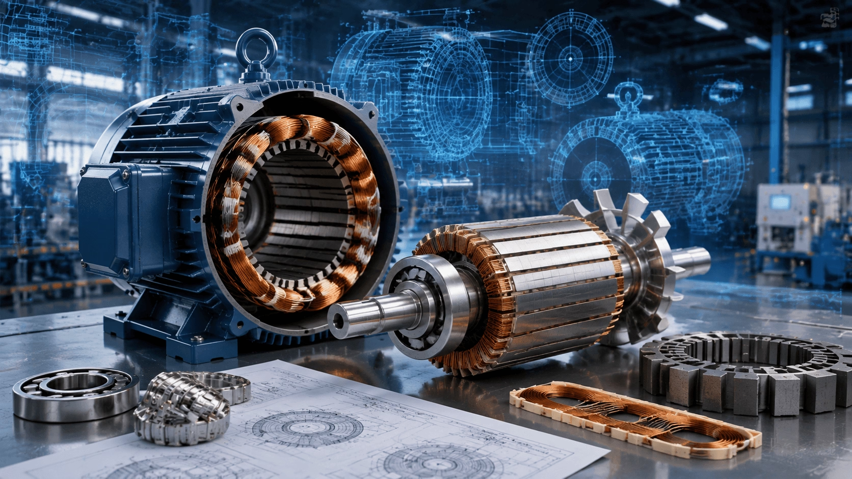
An in-depth technical exploration of stator and rotor engineering in modern three-phase AC motors, encompassing induction and PMSM architectures, advanced materials, thermal management, and multiphysics optimisation. Expert engineering insights from Techo Electrical & Mechanical (Titecho).
1. Introduction
The three-phase AC motor stands as one of the most refined electromechanical devices ever engineered, representing over a century of continuous optimisation. While the fundamental operating principle—Faraday's law of electromagnetic induction—remains unchanged, modern engineering has dramatically advanced the boundaries of efficiency, power density, and reliability through meticulous attention to the two core assemblies: the stator (the stationary electromagnetic engine) and the rotor (the rotating element that converts magnetic energy into mechanical torque).
This guide provides a comprehensive technical examination of the engineering design of modern three-phase AC motor internals, covering both induction and permanent magnet synchronous motor (PMSM) architectures.
2. The Stator: Electromagnetic Architecture
2.1 Core Construction and Lamination Design
The stator core is constructed from silicon steel laminations (typically 0.35–0.65 mm thick) to minimise eddy current losses. Modern high-efficiency motors utilise non-oriented electrical steel with a silicon content of 2–3.5%, which increases electrical resistivity and reduces hysteresis losses while maintaining adequate magnetic permeability.
The lamination stack is assembled according to the following critical design parameters:
| Parameter | Typical Range | Engineering Impact |
|---|---|---|
| Stacking factor | 0.92–0.97 | Higher values reduce air gaps between laminations, improving flux density |
| Slot fill factor | 0.45–0.68 | Determines copper utilisation; higher fill reduces current density and copper losses |
| Tooth flux density | 1.4–1.8 T | Must remain below saturation to prevent excessive core losses |
| Yoke flux density | 1.2–1.6 T | Lower than tooth density to accommodate leakage flux |
The slot geometry represents a critical optimisation variable. Modern designs employ semi-closed or closed slots to reduce air-gap flux pulsation and stray load losses. The number of stator slots (Ss) must be carefully selected relative to rotor slots (Rb) to avoid magnetic noise, synchronous torques, and unbalanced magnetic pull.
2.2 Winding Design: From Distributed to Hairpin
Distributed Windings (Traditional)
The classical three-phase distributed winding consists of coils placed in multiple slots per pole per phase (q). The winding factor (kw), which determines the effective utilisation of the winding, is the product of the pitch factor (kp) and the distribution factor (kd):
kw = kp × kd = [sin(n × α / 2) / (n × sin(α / 2))] × cos(γ / 2)
Where:
- α = Slot pitch angle
- n = Number of slots per pole
- γ = Coil span short-pitching angle
Modern efficiency standards (IE3/IE4) require winding factors exceeding 0.95, driving designers toward higher slot counts and optimised coil pitching to suppress harmonic content.
Hairpin Windings (Next-Generation)
For high-power-density applications—particularly electric vehicle traction motors—hairpin (or formed-wire) windings have emerged as a transformative technology:
- Rectangular copper conductors are pre-formed into U-shapes and inserted into slots.
- Higher slot fill factors (up to 0.75 versus 0.55 for round wire) reduce copper losses by 15–25%.
- Shorter end-turns reduce winding resistance and axial length.
- Direct oil cooling can be integrated between conductors for superior thermal management.
The principal trade-off is increased manufacturing complexity and the requirement for precision laser welding of hairpin connections.
2.3 Insulation Systems
Modern stator insulation must withstand multiple stress mechanisms:
- Thermal stress: Class F (155°C) or Class H (180°C) insulation systems are standard for industrial motors.
- Electrical stress: PWM inverter drives generate steep voltage fronts (dv/dt up to 10 kV/μs), causing partial discharge and insulation ageing.
- Mechanical stress: Thermal cycling and vibration induce insulation abrasion.
Advanced insulation technologies include:
- Mica-based groundwall insulation for medium-voltage motors (> 6.6 kV).
- Nano-filled epoxy resins that improve thermal conductivity and partial discharge resistance.
- Vacuum Pressure Impregnation (VPI) for void-free insulation with superior heat transfer.
3. The Rotor: Where Energy Conversion Occurs
3.1 Squirrel-Cage Induction Motor Rotors
The squirrel-cage rotor remains the most widely deployed rotor design due to its simplicity and robustness.
Bar and End-Ring Design
The rotor comprises conductive bars (aluminium die-cast or copper) embedded in slots and short-circuited by end rings. Key engineering considerations are summarised below:
| Feature | Aluminium Die-Cast | Copper Fabricated |
|---|---|---|
| Manufacturing | High-volume, low cost | Labour-intensive, higher cost |
| Conductivity | ~35 MS/m (lower) | ~58 MS/m (higher) |
| Efficiency impact | Higher rotor losses (~30–40% of total) | Lower rotor losses (~20–25% of total) |
| Starting torque | Moderate | Higher (superior for high-inertia loads) |
| Application | General-purpose industrial | Premium efficiency, high-performance |
Copper rotor die-casting (achieved through proprietary oxygen-free processes) now enables the efficiency benefits of copper at near-aluminium production costs, representing a key enabler for IE4/IE5 efficiency classes.
Slot Design and Performance Optimisation
The rotor slot shape profoundly influences motor performance:
- Deep/narrow slots: Increase rotor leakage inductance, reducing starting current but also starting torque.
- Shallow/wide slots: Lower leakage, higher starting torque, but higher starting current.
- Double-cage slots: Combine high-resistance outer bars for starting torque with low-resistance inner bars for running efficiency.
The number of rotor bars must satisfy strict electromagnetic constraints to avoid synchronous crawling torques, noise, and vibration:
- Rb ≠ Ss (avoid direct slot locking)
- |Ss − Rb| ≠ 2p, 4p, 6p, 10p (prevent synchronous torque spikes)
- Even number of bars preferred to minimise unbalanced magnetic pull
3.2 Wound (Slip-Ring) Rotors
For high-starting-torque or variable-speed applications, wound rotors with three-phase windings connected to external resistors through slip rings remain relevant. Modern slip-ring motors increasingly incorporate:
- Liquid rheostats for smooth resistance variation.
- Cascade (Scherbius/Kramer) drives for slip energy recovery.
- Brushless excitation systems (rotating transformers) to eliminate maintenance-intensive slip rings.
3.3 Permanent Magnet Synchronous Motor (PMSM) Rotors
PMSM rotors represent the cutting edge of modern motor design, delivering the highest efficiency and power density.
Surface-Mounted Magnet (SPMSM)
Magnets are bonded to the rotor surface using high-strength epoxy adhesives:
- Projecting type: Magnets extend above the rotor surface; simplest construction but mechanically weakest.
- Inset type: Magnets are recessed into the rotor with iron poles between them; improved mechanical strength and saliency torque.
Characteristics:
- Nearly equal direct (Ld) and quadrature (Lq) inductances (non-salient).
- Torque produced purely by magnet flux interaction.
- Low inductance necessitates high switching frequency from the inverter.
- Not suitable for high-speed applications due to centrifugal stress on adhesive bonds.
Interior Permanent Magnet (IPMSM)
Magnets are embedded within the rotor laminations:
- V-shape, U-shape, or spoke configurations optimise flux concentration.
- Flux barriers (air or non-magnetic material sections) control magnetic flux paths and enhance saliency.
- High saliency ratio (Lq/Ld > 2) enables significant reluctance torque in addition to magnet torque.
Advantages:
- Mechanical robustness: Magnets are protected from centrifugal forces.
- Higher torque density: Reluctance torque supplements magnet torque.
- Field weakening capability: Negative d-axis current opposes magnet flux, enabling extended speed range.
- Superior demagnetisation withstand: Iron bridges protect magnets from armature reaction.
Advanced IPMSM configurations include:
- Synchronous reluctance-assisted PM motors (SRIPM): Combine PM torque with reluctance torque for reduced rare-earth magnet content.
- Axial-flux configurations: Coreless designs achieving exceptional torque density, though with cooling and structural challenges.
4. The Air Gap: Critical Interface
The air gap between stator and rotor constitutes the most critical dimensional parameter in motor design:
| Motor Type | Typical Air Gap | Design Drivers |
|---|---|---|
| Small induction motors (< 10 kW) | 0.3–0.6 mm | Manufacturing tolerance, mechanical clearance |
| Medium induction motors (10–500 kW) | 0.5–1.5 mm | Balanced against magnetising current |
| Large induction motors (> 500 kW) | 1.5–3.0 mm | Structural deflection, thermal expansion |
| High-speed PMSMs | 0.5–1.0 mm | Mechanical stress, rotor dynamics |
| Large synchronous machines | 5–20 mm | Field winding space, stability |
A smaller air gap reduces magnetising current and improves power factor, but increases:
- Manufacturing precision requirements.
- Risk of rotor-to-stator contact (rubbing).
- Unbalanced magnetic pull sensitivity.
Modern high-performance motors employ automated air gap measurement and active magnetic bearing or self-centering rotor designs to maintain consistent gaps under all operating conditions.
5. Thermal Management: The Hidden Design Driver
5.1 Loss Distribution and Heat Paths
Modern motor design is increasingly thermally limited rather than magnetically limited. The loss breakdown in a premium efficiency induction motor is as follows:
| Loss Component | Typical Share | Primary Location |
|---|---|---|
| Stator copper loss (I²R) | 35–45% | Stator windings |
| Rotor copper/aluminium loss | 15–25% | Rotor bars and end rings |
| Core (iron) loss | 20–30% | Stator and rotor teeth/yoke |
| Stray load loss | 5–15% | End windings, structural parts |
| Friction and windage | 5–10% | Bearings, fan, rotor surface |
5.2 Cooling Architectures
| Cooling Method | Description | Application |
|---|---|---|
| Totally Enclosed Fan Cooled (TEFC) | External fan blows air over ribbed frame | General industrial, outdoor |
| Open Drip Proof (ODP) | Internal ventilation with external air | Clean indoor environments |
| Air-to-Air Heat Exchanger | Closed internal loop with external air cooling | Dirty/hazardous environments |
| Air-to-Water Heat Exchanger | Water cooling for high power density | Large motors, marine |
| Direct Oil Cooling | Oil flows through hollow conductors or rotor passages | Traction motors, aerospace |
| Evaporative Cooling | Phase-change coolant in hollow conductors | Very large generators |
Computational Fluid Dynamics (CFD) and Conjugate Heat Transfer (CHT) analysis are now standard tools for optimising cooling channel geometry and ensuring uniform temperature distribution.
6. Advanced Manufacturing and Materials
6.1 Stator Core Manufacturing
- High-speed stamping: Progressive dies produce laminations at rates exceeding 300 strokes/minute.
- Laser cutting: Enables prototype and low-volume production of complex slot geometries.
- Self-bonding laminations: Adhesive-coated steel eliminates interlaminar insulation varnish, improving stacking factor and heat transfer.
- Amorphous metal cores: Offer 70–80% lower core losses than silicon steel, though with lower saturation flux density and higher cost.
6.2 Winding Insertion Technologies
- Inserting machines: Automated placement of pre-formed coils into stator slots.
- In-slot forming: Round wire windings formed directly in the slot for maximum fill factor.
- Continuous hairpin forming: CNC bending of rectangular conductors with precision tolerances of ±0.1 mm.
6.3 Rotor Manufacturing Innovations
- Copper die-casting: Proprietary oxygen-free processes enable copper cage rotors at production scale.
- Magnet assembly robotics: Precision placement of NdFeB magnets with adhesive dispensing and curing.
- Carbon fibre retaining sleeves: For surface-mounted PM rotors in high-speed applications (turbomachinery, flywheels).
- Additive manufacturing: 3D-printed copper end rings and complex cooling channels for specialised applications.
7. Design Optimisation: The Multiphysics Challenge
Modern motor design requires multiphysics optimisation across electromagnetic, thermal, mechanical, and acoustic domains.
7.1 Electromagnetic Optimisation
- Finite Element Analysis (FEA) of magnetic fields to optimise flux density distribution.
- Genetic algorithms and particle swarm optimisation for multi-objective design (efficiency, cost, weight).
- Torque ripple minimisation through skewing, pole shaping, or current harmonic injection.
7.2 Structural and Rotor Dynamics
At high speeds, centrifugal forces dominate rotor design:
Fc = m × r × ω²
Where:
- Fc = Centrifugal force (N)
- m = Mass of rotating element (kg)
- r = Radius from rotational axis (m)
- ω = Angular velocity (rad/s)
FEA predicts stress distribution in rotor laminations, magnet retainers, and shaft assemblies. Modal analysis ensures that critical speeds (where rotational frequency coincides with natural frequency) remain well outside the operating range.
7.3 Noise, Vibration, and Harshness (NVH)
Electromagnetic noise arises from:
- Radial magnetic forces causing stator ovalisation.
- Torque ripple at slot passing frequencies (f_slot = Nr × f_mech).
- Magnetostriction in core laminations.
Mitigation strategies include:
- Skewing (stator or rotor) by one slot pitch to cancel slot harmonics.
- Fractional slot windings (q < 1) to spread harmonic content.
- Optimised pole/slot combinations following the electromagnetic constraints outlined above.
8. Emerging Trends and Future Directions
8.1 Magnet-Free High-Performance Motors
With rare-earth supply chain concerns, research is intensifying on:
- Synchronous Reluctance Motors (SynRM): Achieve IE4 efficiency without permanent magnets; torque produced entirely through saliency.
- Ferrite-assisted SynRM: Modest ferrite magnets boost torque density at lower cost than NdFeB.
- Alnico-based PM motors: Revival of classical magnet materials with modern design methodologies.
8.2 Integrated Motor-Drive Systems
The boundary between motor and inverter is progressively blurring:
- In-wheel motors with integrated power electronics.
- PCB stators with printed windings and embedded power modules.
- GaN/SiC inverter integration enabling higher switching frequencies and reduced filter requirements.
8.3 Digital Twins and Predictive Maintenance
Modern motors incorporate embedded sensors (temperature, vibration, current signature) feeding digital twin models that:
- Predict remaining useful life.
- Optimise operating points in real time.
- Detect incipient faults (bearing degradation, insulation ageing, rotor bar cracking).
9. Conclusion
The engineering design of modern three-phase AC motors represents a triumph of multidisciplinary optimisation. The stator, with its carefully engineered laminations, optimised windings, and advanced insulation systems, generates the rotating magnetic field that drives the machine. The rotor—whether a simple squirrel cage, a wound winding with slip rings, or a sophisticated permanent magnet assembly—converts that field into mechanical torque with ever-increasing efficiency.
Behind these visible components lies an invisible world of thermal management, structural analysis, and manufacturing precision that determines whether a motor merely functions or excels. As efficiency regulations tighten, electrification accelerates, and digitalisation transforms maintenance paradigms, the fundamental stator-rotor architecture continues to evolve—demonstrating that even after 130 years, the three-phase AC motor retains substantial scope for engineering innovation.
Reference Standards:
- Design standards: IEC 60034 (rotating electrical machines), NEMA MG-1, and IEEE 112
- Thermal design: IEC 60034-18
- Efficiency classes: IEC 60034-30-1 (IE codes) and NEMA Premium efficiency tables
10. Precision Motor Engineering with Titecho
Techo Electrical & Mechanical (Taizhou) Co., Ltd. (Brand: Titecho) specialises in the advanced design and manufacture of three-phase AC induction motors and high-efficiency drive solutions. Our engineering capabilities encompass precision lamination stacking, optimised winding configurations, copper rotor technology, and comprehensive thermal management systems tailored to demanding industrial applications.
We provide complete technical support, including electromagnetic design analysis, thermal modelling, custom material selection, and application-specific optimisation to ensure superior motor performance and reliability.
Explore technical data sheets, engineering specifications, and application support at www.cntecho.com.
© Techo Electrical & Mechanical (Titecho) – Advancing Electromechanical Engineering Excellence