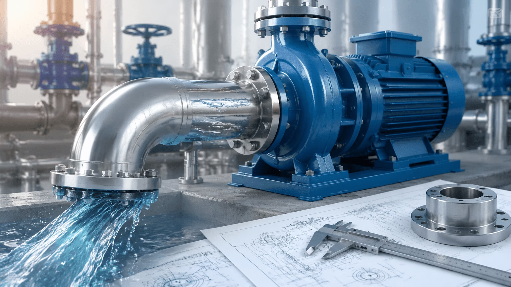
2026 Water Pump Discharge Port Size Guide: Master DN standards, optimal velocity range (1.5–3.0 m/s), selection factors (BEP flow, piping match, fluid type), avoid 6 common sizing mistakes, and optimize system matching—delivered with TECHO professional hydraulic engineering expertise.
Table of Contents
- Core Definitions
- International Standard Specifications
- Discharge Port Size & Pump Performance
- Core Selection Factors
- Common Mistakes & Consequences
- Scenario-Specific Guidelines
- System Optimization Best Practices
- Key Takeaways
Introduction
The water pump discharge port size is a foundational hydraulic parameter that directly dictates fluid delivery capacity, system pressure loss, and overall operational efficiency. A mismatched discharge port size causes:
- Excessive pressure loss and reduced effective head
- Low actual flow rate despite correct pump rating
- Cavitation, pipe vibration, and erosive wear
- Premature pump failure and costly downtime
This guide provides a structured, engineering-grounded framework for selecting the correct discharge port size and ensuring optimal pump-system matching.
1. Core Definitions
In pump engineering and hydraulics, the discharge port size refers to the internal diameter of the pump's outlet connection—the opening through which pressurized fluid is delivered to the piping system. It is a nominal specification governed by international engineering standards.
1.1 Nominal Diameter (DN): The Universal Specification Standard
The Nominal Diameter (DN) is the official, standardized designation under ISO 6708. It is a reference number—not the exact physical internal diameter—expressed in millimeters (e.g., DN25, DN50, DN100).
1.2 Actual Internal Diameter (ID): The Physical Measurement
The Actual Internal Diameter is the precise physical inner width of the discharge port, measured in millimeters or inches. It varies slightly from the nominal DN value based on connection type and manufacturing standards.
1.3 Connection Type and Port Size Compatibility
| Connection Type | Applicable DN Range | Typical Applications | Common Standards |
|---|---|---|---|
| Threaded | DN15–DN50 | Residential, light commercial, small agricultural | NPT (North America), BSPP/BSPT (Europe/Asia) |
| Flanged | DN65–DN300+ | Industrial, large-scale agricultural, municipal | ANSI, DIN, ISO |
| Barb | DN8–DN20 | Micro-pumps, garden irrigation, small sump pumps | Hose clamp / push-fit |
⚠️ Key Warning
Never mix connection standards (e.g., NPT threaded pump port with BSPP pipe fitting) even if the nominal DN size matches. This causes poor sealing, fluid leakage, and flow disturbance at the connection point.
2. International Standard Specifications
Pump discharge port sizes are standardized by ISO 6708 and regional bodies (ANSI, DIN) to ensure global interoperability.
| ISO DN | ANSI Inch Equiv. | Typical Flow Range | Primary Application | Connection Type |
|---|---|---|---|---|
| DN8 | 1/4" | 0.1–1 m³/h | Micro pumps, garden irrigation | Barb / Threaded |
| DN15 | 1/2" | 1–5 m³/h | Residential well pumps, small sump pumps | Threaded (NPT/BSPP) |
| DN20 | 3/4" | 4–10 m³/h | Residential water supply, garden pumps | Threaded (NPT/BSPP) |
| DN25 | 1" | 8–20 m³/h | Light commercial, small agricultural | Threaded (NPT/BSPP) |
| DN40 | 1.5" | 15–40 m³/h | Medium commercial, agricultural irrigation | Threaded / Flanged |
| DN50 | 2" | 30–80 m³/h | Commercial, large agricultural | Threaded / Flanged |
| DN65 | 2.5" | 70–150 m³/h | Light industrial, municipal water supply | Flanged |
| DN80 | 3" | 120–250 m³/h | Industrial, large-scale irrigation | Flanged |
| DN100 | 4" | 200–400 m³/h | Heavy industrial, municipal wastewater | Flanged |
| DN150+ | 6"+ | 400+ m³/h | Large industrial, municipal water treatment | Flanged |
Regional Note: The ANSI inch equivalent is a nominal reference, not the exact physical diameter. The ISO DN size is the only universal designation for international pump procurement.
Manufacturer Sizing Principles:
- Port size is matched to the pump's Best Efficiency Point (BEP) flow rate, ensuring ideal fluid velocity at the outlet.
- Port size is standardized to the nearest ISO DN size for maximum component interoperability.
3. The Critical Relationship Between Discharge Port Size and Pump Performance
The discharge port size directly impacts three core performance metrics: fluid velocity, pressure loss, and actual flow rate.
3.1 Fluid Velocity: The Core Hydraulic Link
Fluid velocity at the discharge port is calculated using the continuity equation:
v = Q / A
where: A = π × (d / 2)²
| Parameter | Definition | Unit |
|---|---|---|
| v | Fluid velocity at discharge port | m/s |
| Q | Pump actual flow rate | m³/s |
| A | Cross-sectional area of discharge port | m² |
| d | Internal diameter of discharge port | m |
Key Correlation: For a fixed flow rate, velocity is inversely proportional to the port's cross-sectional area.
Pump manufacturers design discharge ports to achieve the optimal velocity range for water: 1.5–3.0 m/s.
| Condition | Velocity | Consequence |
|---|---|---|
| Too high | >3.0 m/s | Excessive friction loss, cavitation, pipe vibration, noise, erosive wear |
| Optimal | 1.5–3.0 m/s | Minimal pressure loss, stable operation, long component life |
| Too low | <1.5 m/s | Fluid stagnation, sediment buildup, poor hydraulic performance, bacterial growth risk |
3.2 Pressure Loss: Tied to Port Size and Velocity
Per the Darcy-Weisbach equation, pressure loss increases with the square of fluid velocity. A small velocity increase (from an undersized port) produces a massive pressure loss increase.
Example: A pump with a DN25 port (optimal for 10 m³/h) forced to deliver 20 m³/h will produce a velocity of ~6.8 m/s—more than double the optimal range—resulting in a 4× increase in pressure loss.
3.3 Actual Flow Rate: The Final Performance Outcome
A too-small discharge port creates a hydraulic "bottleneck," restricting delivery and forcing the pump into a vicious cycle:
Smaller port → higher velocity → greater pressure loss → pump works harder → more power drawn → excess heat → accelerated wear → reduced system flow
4. Core Factors for Selecting the Optimal Discharge Port Size
4.1 Pump's Rated Flow Rate (BEP) — Primary Determinant
The BEP flow rate is the single most important factor. Port size is engineered to achieve 1.5–3.0 m/s velocity at BEP.
4.2 Piping System Nominal Size — Critical Matching Factor
The discharge port must match the piping system's nominal DN size. Ideal design: uniform nominal size from pump discharge through the entire piping run.
4.3 Pump's Rated Discharge Head — Pressure Consideration
High-head pumps (≥50 m) require port sizes that minimize pressure loss, as even small losses significantly reduce effective delivered head.
4.4 Fluid Properties — Non-Standard Applications
| Fluid Type | Optimal Velocity | Port Size Adjustment |
|---|---|---|
| Clean / potable water | 1.5–3.0 m/s | Standard DN per BEP |
| High-viscosity fluids | 1.0–2.0 m/s | +1 DN size |
| Dirty water / wastewater | 1.0–2.5 m/s | +1 to +2 DN sizes (clog resistance) |
| High-temperature water | 1.5–2.5 m/s | +1 DN size (reduced viscosity) |
4.5 Application Scenario — Operational Context
Space limitations, noise requirements, and maintenance access impose operational constraints that complement hydraulic design factors.
5. Common Discharge Port Sizing Mistakes
| # | Mistake | Consequence |
|---|---|---|
| 1 | Port smaller than piping system (e.g., DN25 pump on DN50 pipe) | Flow stagnation, velocity <1.5 m/s, sediment buildup, cavitation |
| 2 | Reducer to fit larger port to smaller pipe (e.g., DN50 pump → DN25 reducer) | Velocity >6.0 m/s, excessive pressure loss, vibration, erosive wear |
| 3 | Mixing connection standards (e.g., NPT port + BSPP fitting) | Poor sealing, leakage, air ingestion, reduced flow |
| 4 | Selecting by flow rate alone, ignoring port size | Correct flow/head rating but poor hydraulic performance |
| 5 | Overlooking fluid properties | Clogging, excessive friction loss, reduced flow for non-standard fluids |
| 6 | Sudden offset reducer/expander instead of conical transition | Fluid eddies, dead zones, pressure loss, cavitation, vibration |
Identifying a Mismatched Discharge Port
Watch for these diagnostic indicators:
- Excessive noise or vibration at the discharge connection
- Actual flow rate below the pump's rated BEP flow
- Higher-than-specified energy consumption
- Sediment buildup or fluid stagnation at the outlet
- Leakage or air ingestion at the pump-pipe junction
- Premature wear of impeller, port walls, or pipe fittings
6. Scenario-Specific Discharge Port Size Guidelines
| Application | Recommended DN | Key Matching Tip | Connection Type |
|---|---|---|---|
| Residential (well, sump, garden) | DN15–DN25 | Match port exactly to residential piping size; minimize noise | Threaded (NPT/BSPP) |
| Commercial (buildings, hotels) | DN25–DN50 | Uniform nominal size from pump to main water line | Threaded (DN25–40) / Flanged (DN50) |
| Agricultural Irrigation | DN50–DN80 | Select +1 size above BEP for sediment tolerance | Flanged (DN50+) |
| Industrial (process, cooling) | DN80–DN150+ | Engineer to BEP; match exactly to industrial piping DN | Flanged (ANSI/ISO) |
| Wastewater / Dirty Water | DN50–DN80 (+1–2 sizes) | Prioritize clog resistance; velocity 1.0–2.5 m/s | Flanged (DN50+) |
7. Discharge Port Size Matching & System Optimization
7.1 Follow the "Uniform Nominal Size" Principle
Design the entire hydraulic system with a uniform DN from pump discharge through main piping. For branch lines, use a conical reducer with a 15–30° taper angle.
7.2 Match Piping to Pump (Not the Reverse)
Always select the pump first (based on flow/head requirements), then design piping to match the pump's discharge port. Never select a pump to fit an existing incorrectly sized pipe.
7.3 Use Conical Transitions for Unavoidable Mismatches
- Taper angle: 15–30°
- Transition length: ≥ 3× the difference in nominal diameters
- Never use sudden offset reducers/expanders
7.4 Select Correct Connection Type
| DN Range | Connection | Application Context |
|---|---|---|
| DN8–DN20 | Barb | Small-scale, flexible hose |
| DN15–DN50 | Threaded | Low-pressure, residential/commercial |
| DN65+ | Flanged | High-pressure, industrial/agricultural/wastewater |
7.5 Adjust for Non-Standard Conditions
| Condition | Adjustment |
|---|---|
| Dirty water / wastewater | +1 to +2 DN sizes |
| High-viscosity fluids | +1 DN size |
| High-temperature water | +1 DN size |
| High-pressure systems | Standard DN (minimize loss) |
7.6 Ensure Smooth Internal Surfaces
- Flanged connections: compatible gaskets; flat, parallel flange faces
- Threaded connections: Teflon tape or sealant applied without protruding into the fluid path
- All transitions: smooth, flush internal surfaces to eliminate flow disturbance
7.7 Conduct Hydraulic Calculations for Custom Systems
For custom designs, perform comprehensive hydraulic analysis:
- Confirm pump BEP flow rate and head
- Define fluid properties (viscosity, temperature, solids content)
- Calculate piping pressure loss (Darcy-Weisbach / Hazen-Williams)
- Verify port velocity using the continuity equation: v = Q / A (target: 1.5–3.0 m/s)
- Validate total system head against pump performance curve
8. Key Takeaways
The water pump discharge port size is far more than a fixed pump attribute—it is a critical hydraulic parameter governing delivery capacity, pressure loss, and system efficiency.
-
Port size is engineered to BEP flow rate. The continuity equation (v = Q / A) links port diameter, cross-sectional area, and fluid velocity.
-
Optimal velocity for water systems: 1.5–3.0 m/s. Velocity outside this range leads to hydraulic inefficiencies, cavitation, or sediment buildup.
-
The uniform nominal size principle is the single most effective best practice. Design the entire system at the same DN as the pump's discharge port.
-
When mismatch is unavoidable, use conical transitions (15–30° taper, length ≥ 3× diameter difference).
-
Adjust for fluid properties. Non-standard fluids (viscous, dirty, high-temperature) require +1 to +2 DN sizes.
By mastering core definitions, international standards, and performance relationships, you ensure pump and hydraulic system operate in perfect synergy—delivering maximum flow, minimal pressure loss, and long-term reliability.
Get Custom Discharge Port Size & System Matching Solutions
A mismatched discharge port is a silent killer of hydraulic system efficiency—causing excessive pressure loss, low flow rate, and premature pump failure. Our certified pump and hydraulic engineering specialists provide:
- BEP-based port size verification and selection
- Full hydraulic system matching and pressure loss calculation
- Transition design and connection standard compatibility review
- Non-standard fluid application engineering
[Request Your Custom Port Size Consultation →]
From residential installations to heavy industrial systems, our engineers deliver tailored solutions that eliminate mismatch losses and optimize long-term performance.
© 2026 TECHO Pump & Hydraulic Engineering. All rights reserved.