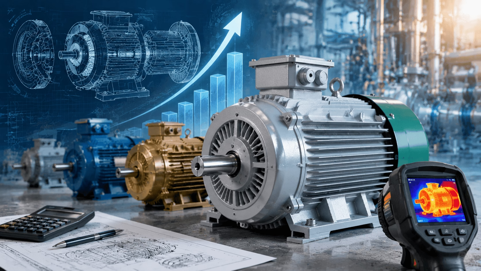
2026 AC Motor Power Guide: Master rated vs. actual output, efficiency classes (IE3/IE4/IE5), kW/HP unit conversions, power factor and active/reactive/apparent power, common selection mistakes, the scientific 7-step method, scenario-specific sizing (pumps, conveyors, compressors), and proven optimization strategies (VFDs, PF correction)—delivered with TECHO engineering expertise.
Table of Contents
- Core Definitions: What Does AC Motor Power Actually Mean?
- International Standard Units & Power Conversions
- AC Power Classification: Active, Apparent & Reactive Power
- Key Factors Affecting Actual Power Output
- Common Selection Mistakes & Scientific Method
- Scenario-Specific Power Selection Guidelines
- Power Optimization & Energy Efficiency Strategies
- Key Takeaways
Introduction
Power is the defining performance parameter of an alternating current (AC) motor, dictating its ability to convert electrical energy into mechanical torque for driving industrial machinery, agricultural equipment, commercial systems, and residential appliances. Misunderstanding AC motor power ratings—or selecting the wrong power for an application—leads to:
- Motor burnout and premature failure
- Excessive energy consumption (30–50% waste from oversizing)
- Poor equipment performance and process disruption
- Costly unplanned downtime
This guide delivers a science-based analysis of AC motor power, covering core definitions, international standard units, critical power classifications, calculation formulas, key factors affecting actual output, common selection mistakes, scenario-specific sizing guidelines, and proven optimization strategies. It is tailored for engineers, plant managers, procurement professionals, and anyone seeking to master AC motor power for optimal system performance and energy efficiency.
1. Core Definitions
Unlike DC motors, AC motor power is not a single static value—it is a set of interrelated ratings describing electrical input, mechanical output, and energy conversion efficiency. The most critical distinction is between nameplate rated power (manufacturer-specified output) and actual operating power (real-world delivered power).
1.1 Rated Output Power (Pn): The Nameplate Core Rating
The rated output power—denoted as Pn—is the mechanical power the motor can continuously deliver at its rated speed, voltage, and frequency, under standard operating conditions (25 °C ambient, ≤1000 m altitude), without exceeding thermal or mechanical limits.
- Expressed in kilowatts (kW) or horsepower (HP)
- Represents the motor's optimal long-term operating capacity
- Tested and certified to international standards (IEC 60034, NEMA MG 1)
1.2 Actual Output Power (Pa): Real-World Performance
The actual output power is the mechanical power delivered to the load in real operating conditions. It is determined entirely by load demand:
- Load < Pn → motor operates at partial power (efficiency drops)
- Load = Pn → motor operates at rated capacity (peak efficiency)
- Load > Pn → motor is overloaded (overheating → premature failure)
1.3 Input Power (Pi): Electrical Power Drawn from Supply
Input power is the total electrical power drawn from the AC supply. It is always higher than output power, as energy is lost as heat, noise, and vibration (copper losses, iron losses, friction losses). Input power (kW) is the key metric for calculating energy consumption and operating costs.
1.4 Motor Efficiency (η): The Energy Conversion Ratio
Efficiency quantifies the motor's ability to convert electrical input to mechanical output:
η = (Po / Pi) × 100%
| Parameter | Definition | Typical Range |
|---|---|---|
| η | Motor efficiency | 75–97% (industrial AC motors) |
| Po | Mechanical output power (kW) | — |
| Pi | Electrical input power (kW) | — |
⚠️ Critical Note: Efficiency is highest at 80–100% of rated load. It drops significantly at low load (≤50% Pn), leading to substantial energy waste.
🛑 Critical Nameplate Warning
An AC motor's nameplate always lists rated output power (mechanical), not input power (electrical). Never confuse the two—this is the single most common mistake in motor power selection and energy cost calculation.
2. International Standard Units & Power Conversions
AC motor power units are standardized by IEC 60034 and NEMA MG 1. Consistent unit usage is critical for international procurement, system design, and performance verification—mixing units leads to costly miscalculations.
2.1 Primary Output Power Units: kW vs. HP
| Power Unit | Abbreviation | Regional / Application Use | Core Conversion Factors |
|---|---|---|---|
| Kilowatt (SI Standard) | kW | Global standard; all IEC motors, industrial design, international procurement | 1 kW = 1.341 Imperial HP; 1 kW = 1.3596 Metric PS |
| Imperial Horsepower | HP (US/UK) | North America, UK, Australia; NEMA motors | 1 HP = 0.7457 kW; 1 HP = 1.0139 Metric PS |
| Metric Horsepower | PS (CV) | Europe, Asia, South America | 1 PS = 0.7355 kW; 1 PS = 0.9863 Imperial HP |
2.2 Electrical Power Units for AC System Design
For AC power system design (wiring, transformers, VFDs), three interrelated power components apply:
| Unit | Symbol | Power Type | Definition |
|---|---|---|---|
| Watt / Kilowatt | W / kW | Active Power | Real power that does useful mechanical work |
| Volt-Ampere / Kilovolt-Ampere | VA / kVA | Apparent Power | Total power drawn from supply (active + reactive) |
| Volt-Ampere Reactive / Kilovar | VAR / kVAR | Reactive Power | Power required to create magnetic field (no useful work) |
2.3 Unit Usage Best Practices
- Use kW for all international motor procurement and industrial system design (IEC global standard).
- Confirm HP type (imperial/metric) when sourcing from North America, Europe, or Asia.
- Use kVA for sizing electrical supply (transformers, cables, VFDs); use kW for motor output and energy cost calculation.
- Convert all regional units to kW before motor selection for consistency.
3. AC Power Classification
AC power consists of three interrelated components—active (P), apparent (S), and reactive (Q) power—forming the foundational power triangle for AC system design.
3.1 Active Power (P): The "Useful" Power
- Measured in W / kW
- The real electrical power converted into mechanical torque
- The only power that does useful work
- Key metric for energy consumption: Energy Cost = kW × Hours × Electricity Rate
3.2 Reactive Power (Q): The "Magnetic" Power
- Measured in VAR / kVAR
- Required to create and maintain the motor's magnetic field (stator and rotor flux)
- Does no useful work—circulates between motor and supply
- AC induction motors are inductive loads drawing significant reactive power
3.3 Apparent Power (S): The Total Supply Power
- Measured in VA / kVA
- Total power drawn from supply: combines active (P) and reactive (Q)
- Used to size all AC electrical supply components (transformers, cables, breakers, VFDs)
- Low PF → more apparent power for same active power → larger supply required
3.4 Power Factor (PF): The AC Efficiency Metric
- Expressed as a decimal (0–1) or percentage (0–100%)
- Ratio of active power to apparent power
- Ideal PF = 1.0 (no reactive power)
- Industrial AC induction motors: PF = 0.75–0.95 at rated load (drops to 0.2–0.5 at low load)
3.5 Core Formulas (Three-Phase)
| Formula | Expression |
|---|---|
| Active Power | P = √3 × V × I × PF |
| Apparent Power | S = √3 × V × I |
| Reactive Power | Q = √(S² − P²) |
| Power Factor | PF = P / S = cosφ |
Parameter Reference:
| Symbol | Definition |
|---|---|
| V | Line-to-line voltage (e.g., 380 V, 400 V, 480 V) |
| I | Line current (A) |
| PF | Power factor (0–1) |
| φ | Phase angle between voltage and current (inductive load: φ > 0) |
Note: For single-phase AC motors (residential/commercial, 110 V / 220 V), omit the √3 factor: P = V × I × PF; S = V × I.
4. Key Factors Affecting Actual Power Output
A motor's actual output power is a dynamic function of six interrelated factors. Understanding their impact is critical for diagnosing poor performance, optimizing efficiency, and preventing premature failure.
4.1 Electrical Supply Voltage (Primary Electrical Factor)
Output power is proportional to the square of the voltage for induction motors—a small voltage drop leads to a large power reduction.
| Condition | Effect |
|---|---|
| 10% under voltage | ~20% reduction in output power; low torque, slow speed, overheating |
| 10% over voltage | Slight power increase; excessive core losses, insulation degradation |
| 5% three-phase unbalance | 20–30% unbalanced current; reduced output; rapid motor failure |
4.2 Load Demand (Primary Mechanical Factor)
| Operating State | Condition | Consequence |
|---|---|---|
| Full Load | 100% Pn | Peak efficiency, optimal temperature |
| Partial Load | ≤80% Pn | Efficiency drops (especially ≤50%); PF deteriorates; energy waste |
| Overload | >100% Pn | Excessive current, overheating, insulation breakdown, burnout |
4.3 Operating Temperature & Environmental Conditions
| Condition | Derating Effect |
|---|---|
| High ambient temperature | ~10% power derating per 10 °C above 25 °C |
| High altitude (>1000 m) | ~1% derating per 100 m increase (reduced cooling) |
| High humidity / corrosive environment | Progressive efficiency loss; requires sealed enclosures |
4.4 Supply Frequency (Hz)
Motor speed is directly proportional to frequency: N = 120f / P (f = frequency, P = pole number). Since Power = Torque × Speed, frequency variations alter both speed and power output.
- Low frequency → reduced speed and power (used intentionally with VFDs)
- High frequency → increased speed; excessive vibration and mechanical stress
4.5 Motor Age & Wear
Unmaintained motors can lose 10–30% of rated power after 5–10 years:
- Worn bearings → increased friction loss
- Degraded winding insulation → copper losses and current leakage
- Contaminated enclosure → blocked cooling, overheating
- Increased rotor/stator air gap → reduced magnetic flux and torque
4.6 Power Factor & Electrical System Design
Low PF increases apparent power (kVA) and system current for the same active power (kW), creating additional losses. Poor system design (undersized cables, uncorrected PF) reduces effective power delivered to the motor.
5. Common Selection Mistakes & Scientific Method
Over 70% of industrial AC motors are oversized—the single biggest selection mistake—leading to massive energy waste, low efficiency, and poor power factor.
5.1 The 5 Most Common Mistakes
| # | Mistake | Consequence |
|---|---|---|
| 1 | Oversizing for "safety" (20–50% excess) | Operation at ≤50% Pn; efficiency and PF drop drastically; 30–50% energy waste |
| 2 | Undersizing for cost savings | Continuous overload; excessive current; burnout in days/weeks |
| 3 | Ignoring peak load demand | Overload during startup/transient peaks despite normal partial-load operation |
| 4 | Neglecting environmental derating | Overheating and insufficient power delivery despite correct nominal rating |
| 5 | Confusing kW and kVA | Insufficient mechanical power despite correct electrical supply sizing |
5.2 Scientific 7-Step Power Selection Method
Aligned with IEC 60034 and NEMA MG 1. Target: motor operates at 80–100% load (peak efficiency).
| Step | Action | Detail |
|---|---|---|
| 1 | Calculate actual load power (Pl) | Measure/calculate continuous steady-state power. Example (pump): Pl = Q × H × ρ / (ηp × 3600), where Q = flow (m³/h), H = head (m), ρ = density (kg/m³), ηp = pump efficiency |
| 2 | Account for peak load (Ppeak) | Calculate startup/transient/maximum load; ensure ≤150% of continuous load |
| 3 | Apply contingency factor (10–15%) | Multiply Pl by 1.10–1.15 for minor variations and small expansion. Avoid >20% |
| 4 | Calculate derated power (Pd) | Adjust for environment using manufacturer's derating curve: Pd = Pn × derating factor |
| 5 | Select rated motor power (Pn) | Choose Pn equal to or 5–10% above Pd. Verify peak torque capacity matches load |
| 6 | Verify efficiency & PF | Select IE3/IE4/IE5 class; PF ≥ 0.85 at 80% load |
| 7 | Validate with a motor engineer | For complex loads (variable torque, high startup), obtain certified engineering review |
6. Scenario-Specific Power Selection Guidelines
Different applications have unique load characteristics. A motor sized for a pump (variable torque) will not perform for a conveyor (constant torque), even at identical nominal power.
| Application | Load Type | Startup Torque | Power Sizing Tip | Key Note |
|---|---|---|---|---|
| Industrial Pumps & Fans | Variable torque (T ∝ speed²) | 100–150% rated | Match peak flow/head; 10% contingency max | Oversizing wastes massive energy; use VFDs; IE4/IE5 |
| Conveyors & Elevators | Constant torque | 150–200% rated | Match continuous torque; 15% contingency | Verify peak torque for startup safety |
| Compressors & Hydraulics | High startup; constant power at speed | 200–300% rated | Prioritize peak torque capacity over nominal power | Use soft starters or VFDs |
| Agricultural Equipment | Variable torque; harsh environment | 100–150% rated | Size for peak season; apply environmental derating | IP55/IP65 enclosures; derate 10–15% for heat/dust |
| Commercial HVAC & Pumps | Variable torque; continuous operation | 100–150% rated | Match peak building demand; use VFDs | IE3/IE4 minimum (code-mandatory) |
| Residential Appliances | Low power; single-phase; intermittent | — | Use OEM-specified power (factory-sized) | Fractional HP (0.25–1 HP) / 0.18–0.75 kW standard |
7. Power Optimization & Energy Efficiency Strategies
Once correctly selected, optimizing actual power output and efficiency reduces operating costs, lowers emissions, and extends motor life.
7.1 Correct Power Factor – Low Cost, High Impact
The single most effective low-cost optimization for industrial AC induction motors. Saves 5–15% on electrical costs.
- Capacitor banks — install shunt capacitors near motor; supply reactive power locally. Target PF = 0.95 (lagging).
- Static Var Compensators (SVC) — dynamic PF correction for large systems with variable load.
7.2 Use Variable Frequency Drives (VFDs) – Medium Cost, Maximum Savings
The gold standard for variable torque loads. Saves 20–50% on electrical costs for continuously operating motors.
- For variable torque: Power consumption ∝ speed³ — reducing speed by 20% cuts power by ~50%.
- Additional benefits: soft start/stop, precise speed control, extended motor life.
7.3 Replace Oversized/Old Motors with Premium Efficiency Models
Replacing IE1/IE2 or oversized (≤50% load) motors with IE3/IE4/IE5 models yields payback periods of 1–3 years for continuous operation (5–20% higher efficiency).
Key Tip: Resize the motor to match actual load demand when replacing—this maximizes efficiency gains.
7.4 Implement Scheduled Preventive Maintenance
Unmaintained motors lose 10–30% efficiency over time. Well-maintained motors retain >95% rated performance for 10–20 years.
- Lubricate bearings per manufacturer schedule
- Clean enclosures and cooling vents
- Inspect winding insulation and connections annually
- Perform laser shaft alignment
7.5 Stabilize the Electrical Supply
- Install voltage stabilizers (±5% tolerance)
- Use phase balancers for three-phase systems (≤2% unbalance)
- Install surge protectors against voltage spikes and transients
7.6 Match Motor Enclosure to Operating Environment
| IP Rating | Application |
|---|---|
| IP55 / IP65 | Dust-proof / water-resistant; industrial and agricultural outdoor use |
| IP66 / IP67 | Waterproof / dust-tight; washdown environments (food, chemical) |
| TEFC | Standard industrial; prevents contamination and cooling loss |
8. Key Takeaways
AC motor power is the most critical—and most commonly misunderstood—parameter for motor selection, operation, and efficiency. The core principles are:
-
AC motor power is not a single value. It is a set of interrelated ratings (rated/actual, input/output, active/apparent/reactive) governed by supply conditions, load demand, and environment.
-
Oversizing is the #1 mistake. It wastes 30–50% energy at low load, degrades PF, and increases operating costs. The scientific method—calculating actual/peak load, applying 10–15% contingency, and accounting for derating—eliminates this error.
-
Optimization is as important as selection. PF correction, VFDs, premium efficiency motors, and preventive maintenance reduce energy costs by 5–50%.
-
Load characteristics dictate selection. Variable torque, constant torque, and high startup loads require fundamentally different power and torque considerations—not just nominal kW/HP.
A well-selected, well-maintained AC motor operating at 80–100% load will deliver optimal power, efficiency, and reliability throughout its design life.
Master AC Motor Power with Professional Engineering Expertise
Incorrect AC motor power selection and poor optimization lead to excessive energy costs, premature failure, and costly downtime—costs that accumulate to thousands annually. Our certified electrical and motor engineering specialists offer:
- Precise load power calculation and scientific motor sizing
- Power factor correction and VFD installation
- Preventive maintenance program design
- Full system efficiency audits
[Request Your Custom AC Motor Power Consultation →]
From new motor selection to existing system optimization, we tailor solutions to your unique load characteristics, operating conditions, and performance goals.
© 2026 TECHO Pump & Motor Engineering. All rights reserved.