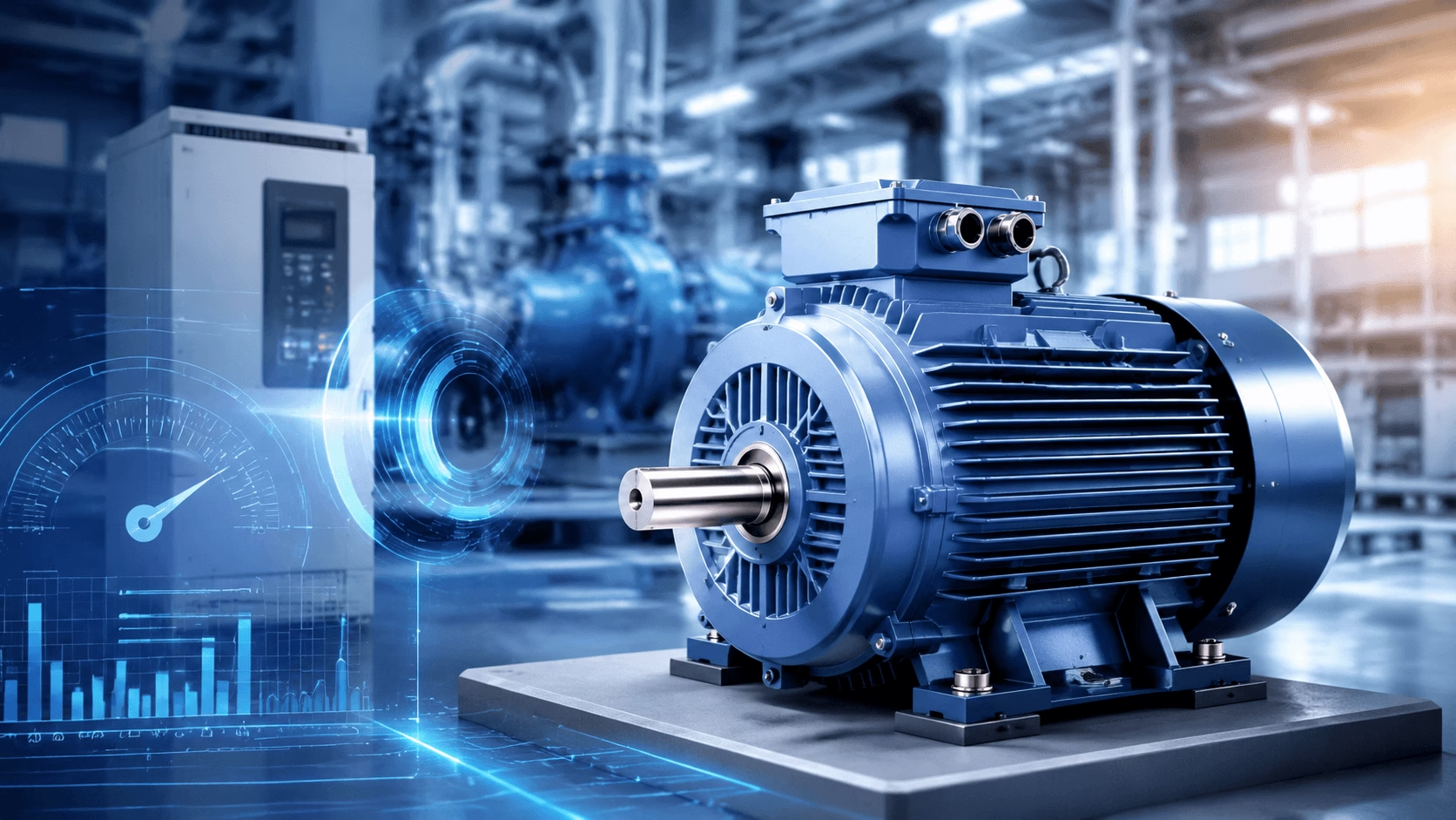
2026 AC Motor Speed Guide: Synchronous speed formula, slip in induction motors, RPM ratings (IEC/NEMA), VFD control, 6 critical selection mistakes, scenario-specific tips (pumps/fans/CNC), and advanced optimization strategies for maximum efficiency — compiled with TECHO engineering expertise.
Introduction: The Central Role of Speed in AC Motor Performance
Speed is the critical bridge between an AC motor's electrical input and its mechanical output. It dictates how quickly electrical energy is converted into rotational motion, how effectively the motor drives connected industrial equipment, and whether the system delivers the precise torque required for every application. Unlike fixed parameters such as voltage rating or insulation class, AC motor speed is a dynamic characteristic governed by fundamental electromagnetic principles, motor construction geometry, and the sophistication of the control systems employed.
In modern industrial environments—ranging from municipal water treatment plants to semiconductor fabrication facilities—the ability to precisely understand, select, control, and optimize AC motor speed directly determines operational efficiency, product quality, energy expenditure, and equipment longevity. A misjudgment of even 2–3% in speed selection can cascade into significant process deviations, accelerated mechanical wear, and substantial financial losses over the motor's operational lifetime.
This guide provides a rigorous, standards-aligned treatment of AC motor speed fundamentals, control methodologies, selection science, and optimization strategies, drawing upon IEC 60034, NEMA MG 1, and contemporary industrial best practices as of 2026.
Core Definitions: Mastering AC Motor Speed Fundamentals
AC motor speed is defined by a set of interrelated engineering terms and physical principles that form the foundation of all motor operation. Confusion between these core concepts is the leading cause of speed-related motor failures, inefficient system design, and costly unplanned downtime. A thorough command of the following definitions is indispensable for any engineer, technician, or procurement specialist working with AC drive systems.
1. Rated Speed (n_n): The Motor's Designated Operating Speed
The rated speed (n_n)—prominently marked on every AC motor's nameplate—is the rotational speed (measured in revolutions per minute, RPM) at which the motor operates continuously under IEC 60034 and NEMA MG 1 standard conditions. These standard conditions include:
- Rated voltage and frequency applied to the stator terminals
- Rated mechanical load torque applied to the output shaft
- Ambient temperature not exceeding 40 °C (per IEC 60034-1)
- Altitude not exceeding 1000 m above sea level
- Continuous duty cycle (S1) operation
The rated speed represents the equilibrium point at which the motor's electromagnetic torque exactly balances the sum of the load torque and internal friction losses. It is the speed at which the motor achieves its nameplate efficiency and power factor ratings. Operating persistently above or below rated speed will shift the motor away from its designed thermal and electromagnetic operating envelope, accelerating insulation degradation and reducing service life.
2. Synchronous Speed (n_s): The Speed of the Stator's Rotating Magnetic Field
Synchronous speed (n_s) is the theoretical rotational speed of the magnetic field generated by the motor's stator windings. This rotating magnetic field—produced by the spatial and temporal phase displacement of the three-phase (or single-phase) AC currents flowing through the stator coils—sweeps around the air gap at a rate determined exclusively by the AC supply frequency (f) and the motor's number of magnetic poles (P). No mechanical load, voltage variation, or temperature change can alter synchronous speed; only a change in supply frequency or a physical reconfiguration of pole connections can do so.
Synchronous Speed Formula (Universal for All AC Motors)
n_s = (120 × f) / P
Where:
| Symbol | Definition | Unit |
|---|---|---|
| n_s | Synchronous speed | revolutions per minute (RPM) |
| f | AC supply frequency | Hertz (Hz) — 50 Hz (Europe, Asia, Africa, most of South America) or 60 Hz (North America, Mexico, parts of South America, Saudi Arabia) |
| P | Number of motor magnetic poles | always an even integer: 2, 4, 6, 8, 10, 12, etc. |
| 120 | Dimensional constant | derived from unit conversions: 60 seconds/minute × 2 (because each AC cycle produces one north and one south pole passage) |
Worked Example: A 4-pole motor connected to a 50 Hz supply produces a synchronous speed of:
n_s = (120 × 50) / 4 = 6000 / 4 = 1500 RPM
The same 4-pole motor on a 60 Hz supply yields:
n_s = (120 × 60) / 4 = 7200 / 4 = 1800 RPM
This 20% speed differential between 50 Hz and 60 Hz systems is a critical consideration in international equipment procurement and cross-border industrial projects.
3. Asynchronous Speed (n_r): The Actual Rotor Speed of Induction Motors
Asynchronous speed (n_r)—also termed rotor speed or actual speed—is the measured rotational speed of the rotor shaft in an induction (asynchronous) motor. Induction motors account for over 90% of all industrial and commercial AC motor installations worldwide, making asynchronous speed the most practically relevant speed parameter in the field.
The rotor in an induction motor can never reach synchronous speed under load. If it did, there would be zero relative motion between the rotating stator field and the rotor conductors, zero induced electromotive force (EMF) in the rotor bars, zero rotor current, and consequently zero electromagnetic torque. The rotor must therefore "slip" behind the stator field to sustain torque production. This inherent speed deficit is not a defect; it is the fundamental operating principle of the induction machine.
4. Slip (s): The Critical Torque-Generating Speed Difference
Slip (s) is the dimensionless ratio expressing the difference between synchronous speed and actual rotor speed, normalized to synchronous speed. It is expressed either as a percentage or as a decimal fraction.
Slip Formula (Induction Motors Only — IEC/NEMA Standard)
s = [(n_s − n_r) / n_s] × 100%       (Percentage Slip)

s = (n_s − n_r) / n_s                 (Decimal Slip)
Worked Example: A 4-pole, 50 Hz induction motor has a synchronous speed of 1500 RPM and an actual measured rotor speed of 1470 RPM under rated load.
s = [(1500 − 1470) / 1500] × 100%
s = [30 / 1500] × 100%
s = 0.02 × 100%
s = 2%
Typical full-load slip values for standard IEC/NEMA induction motors range from 0.5% to 5%, depending on motor size, design class, and pole number. Smaller motors (below 1 kW) tend toward higher slip (3–5%), while large motors (above 100 kW) exhibit very low slip (0.5–1.5%).
⚠️ Critical Engineering Note:
Slip is not an energy loss—it is a mandatory design feature of induction motors and the physical mechanism by which torque is generated. However, excessive slip (above 5–7% under rated load) is a definitive diagnostic indicator of a critical issue: motor overloading, supply under-voltage, damaged or shorted stator/rotor windings, broken rotor bars, or severely worn mechanical components. Persistent high-slip operation accelerates thermal aging of insulation and can lead to catastrophic winding failure within weeks.
Synchronous vs. Asynchronous Speed: Key Differences & Applications
All AC motors fall into two primary categories based on their speed characteristics: synchronous motors and asynchronous (induction) motors. Understanding the fundamental behavioral differences between these two classes is essential for correct application engineering.
| Performance Characteristic | Synchronous AC Motors | Asynchronous (Induction) AC Motors |
|---|---|---|
| Speed Relationship | Rotor speed equals synchronous speed (n_r = n_s); slip = 0 | Rotor speed is less than synchronous speed (n_r < n_s); slip = 0.5–5% |
| Speed Stability | Exceptionally stable; zero speed variation with load changes (up to pull-out torque) | Moderate stability; speed decreases progressively as load torque increases |
| Efficiency (Rated Load) | Ultra-high: 95–98% (PM synchronous); 94–97% (wound-field synchronous) | High: 90–97% for IE3/IE4/IE5 models |
| Power Factor | Adjustable (can operate at unity or leading PF with excitation control) | Lagging; typically 0.80–0.92 at rated load |
| Starting Method | Requires auxiliary starting (damper windings, VFD, or pony motor) | Self-starting (direct-on-line, star-delta, soft starter, or VFD) |
| Cost Profile | Higher upfront cost (20–60% premium); lower lifetime energy cost | Lower upfront cost; moderate lifetime energy cost |
| Maintenance | Higher (brushes/slip rings on wound-field types; PM types are low-maintenance) | Lower (squirrel-cage type has no brushes, slip rings, or commutator) |
| Typical Applications | Large compressors, synchronous condensers, precision drives, marine propulsion | Pumps, fans, conveyors, machine tools, HVAC, general industrial drives |
⚠️ Common Application Mistake:
Deploying a standard squirrel-cage induction motor for precision industrial applications (e.g., CNC spindle drives, robotic assembly lines, optical fiber drawing) will inevitably lead to poor process control, dimensional inaccuracies, and product defects due to the inherent speed variation with load (slip). For such applications, a permanent magnet synchronous motor (PMSM) with closed-loop servo control is the technically correct choice.
International Standard AC Motor Speed Ratings (IEC & NEMA)
1. IEC Standard Speed Ratings (Global, 50 Hz Supply)
The following table presents the standard synchronous and rated speeds for IEC 60034-compliant three-phase induction motors operating on a 50 Hz supply:
| Number of Poles (P) | Synchronous Speed (n_s, RPM) | Rated Speed (n_n, RPM) — IE3 Induction Motor | Typical Full-Load Slip |
|---|---|---|---|
| 2 | 3000 | 2940 – 2970 | 1.0 – 2.0% |
| 4 | 1500 | 1470 – 1485 | 1.0 – 2.0% |
| 6 | 1000 | 970 – 985 | 1.5 – 3.0% |
| 8 | 750 | 720 – 740 | 1.3 – 4.0% |
| 10 | 600 | 575 – 592 | 1.3 – 4.2% |
| 12 | 500 | 478 – 493 | 1.4 – 4.4% |
2. NEMA Standard Speed Ratings (North America, 60 Hz Supply)
| Number of Poles (P) | Synchronous Speed (n_s, RPM) | Rated Speed (n_n, RPM) — NEMA Design B | Typical Full-Load Slip |
|---|---|---|---|
| 2 | 3600 | 3540 – 3570 | 0.8 – 1.7% |
| 4 | 1800 | 1760 – 1785 | 0.8 – 2.2% |
| 6 | 1200 | 1160 – 1185 | 1.3 – 3.3% |
| 8 | 900 | 865 – 890 | 1.1 – 3.9% |
3. Key Regional Speed & Frequency Considerations
-
50 Hz vs. 60 Hz Compatibility: A motor designed and nameplated for 50 Hz operation cannot be directly connected to a 60 Hz supply without a Variable Frequency Drive (VFD). Doing so will increase synchronous speed by 20%, reduce available torque, alter the V/Hz ratio, and risk magnetic saturation or insulation overstress. Conversely, a 60 Hz motor on a 50 Hz supply will run 20% slower and may overheat due to reduced cooling fan effectiveness and altered impedance.
-
Dual-Frequency Global Motors: IEC/NEMA dual-frequency motors (e.g., nameplated "50/60 Hz, 4-pole, 1450/1740 RPM") are specifically engineered for international industrial projects, export machinery, and multinational facility standardization. These motors incorporate winding designs and thermal margins that accommodate both frequency regimes.
-
NEMA Design Classes: NEMA MG 1 defines four standard torque-speed design classes:
- Design A: Normal starting torque, normal starting current, low slip (< 5%).
- Design B: Normal starting torque, reduced starting current, low slip (< 5%). The most common general-purpose class.
- Design C: High starting torque (up to 250% of rated), reduced starting current, moderate slip (3–5%). Suited for hard-starting loads such as loaded conveyors and positive displacement pumps.
- Design D: Very high starting torque (up to 280%), high slip (5–8%). Used for high-inertia loads such as punch presses, oil well pumps, and flywheel-driven equipment.
Factors Affecting AC Motor Speed: What Causes Speed Variations?
A comprehensive understanding of all variables that influence AC motor speed is essential for accurate diagnosis, proper selection, and effective troubleshooting. The following six factors represent the complete set of primary and secondary influences.
1. Supply Frequency (f): The Most Critical Determinant
AC supply frequency is the single most important factor affecting motor speed. Synchronous speed—and thus all operational speed—is directly proportional to frequency (n_s ∝ f) per the universal synchronous speed formula. A 1% change in supply frequency produces a 1% change in synchronous speed. In practice, utility grid frequency is tightly regulated (±0.1 Hz in most developed nations), but in regions with unstable grids or on generator-supplied sites, frequency excursions of ±1–2% are common and will produce measurable speed deviations.
2. Mechanical Load Torque: The Primary Variable Factor
Mechanical load torque—the resistance the motor must overcome to rotate connected equipment—is the primary variable factor affecting AC motor speed in induction machines. As load torque increases, the rotor decelerates slightly, slip increases, and the induced rotor current rises to produce additional electromagnetic torque. This self-regulating mechanism is elegant but finite: if load torque exceeds the motor's breakdown (pull-out) torque—typically 200–350% of rated torque—the motor will stall abruptly, drawing locked-rotor current (5–8 times rated current) and tripping protective devices within seconds.
3. Supply Voltage: An Indirect but Significant Factor
Supply voltage does not directly affect synchronous speed (which is determined solely by frequency and pole number). However, it indirectly impacts motor speed by influencing the motor's torque-producing capability. Electromagnetic torque in an induction motor is proportional to the square of the applied voltage (T ∝ V²). A 10% reduction in supply voltage produces approximately a 19% reduction in available torque, forcing the motor to operate at higher slip to maintain equilibrium with the load, thereby reducing actual speed. Sustained undervoltage operation also increases stator and rotor copper losses, elevating winding temperature and accelerating insulation aging.
4. Number of Magnetic Poles (P): A Fixed Design Factor
The number of magnetic poles in the motor is a fixed design characteristic determined at manufacture by the stator winding configuration. It has an inverse relationship with synchronous speed (n_s ∝ 1/P): more poles yield a lower synchronous speed, and fewer poles yield a higher synchronous speed. Pole number cannot be changed in a standard motor without physically rewinding the stator. However, specially designed pole-changing motors (Dahlander or consequent-pole windings) permit switching between two discrete pole configurations (e.g., 4-pole/8-pole, yielding 1500/750 RPM at 50 Hz) via external contactor switching.
5. Temperature: A Hidden Performance Degrader
Ambient and operating temperature affect AC motor speed through several mechanisms:
- Increased winding resistance: Copper resistance rises approximately 0.393% per °C. Higher resistance increases I²R losses, reducing the voltage available for torque production and slightly increasing slip.
- Magnetic property degradation: Permanent magnets in PMSM and synchronous reluctance motors lose flux density at elevated temperatures (NdFeB magnets lose approximately 0.12% flux per °C above 80 °C), reducing torque capability.
- Bearing lubricant viscosity changes: Extreme cold increases grease viscosity, raising friction torque; extreme heat thins lubricant, risking metal-to-metal contact.
- Thermal expansion: Differential expansion between rotor and stator can alter air gap dimensions, affecting magnetic coupling.
For every 10 °C increase in sustained operating temperature above the insulation class rating, motor insulation life is approximately halved (the Arrhenius "10-degree rule" per IEC 60034-18).
6. Mechanical Issues: Bearing Wear, Misalignment & Friction
Mechanical problems are a major but frequently undiagnosed cause of AC motor speed variations. Common mechanical culprits include:
- Worn or damaged bearings: Increase friction torque by 15–40%, causing measurable speed reduction and characteristic vibration signatures (BPFO, BPFI frequencies).
- Shaft misalignment: Angular or parallel misalignment between motor and driven equipment shafts introduces cyclic loading, increases bearing stress, and can reduce effective speed by 1–3%.
- Excessive gear or belt friction: Worn gear teeth, overtensioned V-belts, or contaminated lubricant in gearboxes add parasitic load.
- Seized or binding components: Corroded couplings, foreign object ingress, or thermal seizure of rotating elements can cause progressive speed loss culminating in stall.
Vibration analysis (ISO 10816 / ISO 20816) and infrared thermography are the primary diagnostic tools for identifying mechanical speed-degrading faults before they cause catastrophic failure.
AC Motor Speed Control Methods: Proven Techniques for Precision & Efficiency
1. Variable Frequency Drives (VFDs): The Gold Standard for Speed Control
Variable Frequency Drives (VFDs)—also called Adjustable Frequency Drives (AFDs), Adjustable Speed Drives (ASDs), or Inverters—are the most versatile, efficient, and precise method for controlling AC motor speed. They are the undisputed industry standard for modern industrial applications as of 2026.
Operating Principle: A VFD converts fixed-frequency, fixed-voltage AC input to DC via a rectifier stage, filters the DC through a capacitor bank (DC bus), and then synthesizes a variable-frequency, variable-voltage AC output via an IGBT (Insulated-Gate Bipolar Transistor) inverter stage using Pulse Width Modulation (PWM). By maintaining a constant V/Hz ratio (for scalar control) or employing vector/field-oriented control (FOC), the VFD precisely governs motor speed and torque across the entire operating range.
Key Advantages:
- Precise speed control: ±0.1–1% accuracy (open-loop); ±0.01% with encoder feedback (closed-loop)
- Energy savings: 20–50% for variable-torque loads (pumps, fans) via the affinity laws (power ∝ speed³)
- Soft start/stop: Reduces inrush current by 50–70% compared to direct-on-line starting, eliminating mechanical shock
- Regenerative braking capability (with appropriate front-end topology)
- Integrated motor protection (overcurrent, overvoltage, undervoltage, ground fault, thermal overload)
- Communication protocols: Modbus, PROFINET, EtherNet/IP, EtherCAT for Industry 4.0 integration
Ideal Applications: CNC machines, industrial robotics, centrifugal pumps, axial and centrifugal fans, belt and screw conveyors, reciprocating and screw compressors, HVAC chillers and air handlers, extruders, winding/unwinding lines, and crane/hoist drives.
2. Pole Changing: Low-Cost Fixed-Speed Step Control
Pole changing is a simple, robust, and low-cost speed control method limited to induction motors with specially designed stator windings (Dahlander/consequent-pole or separate-winding configurations) that allow switching between two or more discrete magnetic pole configurations via external contactors.
- Typical configurations: 2-speed (e.g., 4/8-pole: 1500/750 RPM at 50 Hz) or 3-speed (e.g., 4/6/8-pole: 1500/1000/750 RPM).
- Advantages: No power electronics required; high efficiency at each discrete speed; low maintenance; robust in harsh environments.
- Limitations: Only 2 or 3 fixed speeds available; no continuous speed variation; torque characteristics change between pole configurations; transient current spikes during pole switching.
- Applications: Multi-speed machine tool spindles, elevator drives, cooling tower fans with seasonal speed requirements, crane hoists.
3. Voltage Control: Simple Low-Speed Induction Motor Control
Voltage control—also called AC voltage regulation—is a simple, low-cost method for controlling the speed of small single-phase and low-power three-phase induction motors (typically ≤ 5 kW). It employs autotransformers, triac-based AC regulators, or saturable reactors to reduce the RMS voltage applied to the stator, thereby reducing available torque and increasing slip.
- Advantages: Very low cost; simple circuitry; no frequency conversion required.
- Limitations: Very limited speed range (typically 10–20% below rated speed); poor efficiency at reduced speeds (high slip losses); reduced torque capability (T ∝ V²); not suitable for constant-torque loads; generates harmonics (triac-based).
- Applications: Small domestic fans, table saws, low-power conveyor drives, laboratory stirrers.
4. Rotor Resistance Control: High-Torque Induction Motor Control
Rotor resistance control is a specialized speed control method for wound rotor induction motors (WRIMs)—a type of induction motor with a three-phase wound rotor connected to external variable resistors via slip rings and carbon brushes.
- Operating Principle: Inserting external resistance into the rotor circuit increases the slip at which maximum torque occurs, allowing the motor to operate stably at reduced speeds while maintaining high torque output.
- Advantages: Very high starting torque (up to 300% rated); smooth acceleration of high-inertia loads; simple control architecture.
- Limitations: Significant energy dissipation in external resistors (efficiency drops proportionally with slip); brush and slip ring maintenance; limited speed range; largely superseded by VFDs in new installations.
- Applications: Large ball mills, rotary kilns, ship anchor windlasses, legacy crane and hoist installations, large compressor starting.
5. Gear Reducers: Mechanical Speed Reduction (Non-Electrical Control)
Gear reducers—also called gearboxes, speed reducers, or gear trains—are a purely mechanical speed control method used in conjunction with standard fixed-speed (or VFD-driven) AC motors to achieve low output speeds with proportionally multiplied torque.
- Common types: Helical gear reducers, planetary gear reducers, worm gear reducers, cycloidal reducers, harmonic drive reducers.
- Advantages: Extremely high reduction ratios (up to 10,000:1 for harmonic drives); torque multiplication; no electrical complexity; high reliability; compatible with any motor type.
- Limitations: Fixed ratio (unless combined with VFD); backlash (affects positioning accuracy); lubrication maintenance; noise at high ratios; efficiency losses (85–97% per stage).
- Applications: Conveyor drives, mixers, agitators, packaging machinery, robotic joints, turntables, low-speed high-torque process equipment.
💡 Industrial Speed Control Selection Rule:
For all industrial applications requiring variable speed or precision control (which constitutes approximately 90% of modern industrial drive requirements), a VFD is always the optimal choice—even accounting for its higher upfront cost relative to simpler methods. The energy savings (20–50% on variable-torque loads), reduced mechanical stress (soft start/stop), extended motor and driven-equipment life, and integrated diagnostic capabilities provided by a VFD will typically recoup the initial investment within 1–3 years of continuous operation.
AC Motor Speed Selection: Common Mistakes & Scientific Method
The 6 Most Common AC Motor Speed Selection Mistakes
-
Mistake 1 — Speed-RPM Mismatch: Selecting a motor whose rated speed is significantly higher or lower than the application's required operational speed. An oversized-speed motor will operate at light load with poor efficiency and power factor; an undersized-speed motor will be perpetually overloaded, overheating and failing prematurely.
-
Mistake 2 — Ignoring Load Torque Characteristics: Selecting a motor based solely on speed (RPM) without analyzing the load torque profile (constant torque, variable torque, or constant power). A centrifugal pump (variable torque: T ∝ n²) has fundamentally different motor requirements than a conveyor (constant torque) or a machine tool spindle (constant power above base speed).
-
Mistake 3 — Wrong Control Method Selection: Employing a low-cost, imprecise control method (e.g., voltage control or pole changing) for an application demanding tight speed regulation (e.g., ±0.5% for a printing press). This results in chronic product quality issues and process instability.
-
Mistake 4 — 50 Hz / 60 Hz Frequency Incompatibility: Installing a motor designed for 50 Hz on a 60 Hz supply (or vice versa) without an intervening VFD. This produces a 20% speed error, altered V/Hz ratio, potential magnetic saturation, reduced torque, and accelerated thermal aging.
-
Mistake 5 — High-Pole Motor for Low-Speed Applications: Specifying a custom 12-pole or 16-pole motor for a low-speed application (e.g., 400 RPM) instead of using a standard 4-pole motor with a gear reducer. High-pole motors are larger, heavier, more expensive, less efficient, and have poorer power factor than equivalent low-pole motors with mechanical reduction.
-
Mistake 6 — Induction Motor for Precision Constant-Speed Applications: Deploying a standard squirrel-cage induction motor for precision applications requiring absolute constant speed regardless of load variation (e.g., synchronous generators, precision grinding spindles, optical encoders). The inherent slip characteristic makes this technically unsuitable; a synchronous motor or PMSM with servo drive is required.
Step-by-Step Scientific Speed Selection Method (IEC/NEMA Aligned)
Step 1 — Define Application Speed & Torque Requirements:
Calculate the exact required operational speed (RPM) at the driven equipment shaft and the maximum continuous and peak load torque (N·m). Include acceleration torque for high-inertia loads. Characterize the load as constant torque, variable torque (affinity law), or constant power.
Step 2 — Identify Supply Frequency & Voltage:
Confirm the installation site's AC supply frequency (50 Hz or 60 Hz), voltage (e.g., 400 V, 480 V, 690 V), phase configuration (3-phase or single-phase), and available short-circuit capacity. Verify power quality (THD, voltage unbalance per IEC 60034-26).
Step 3 — Calculate Required Synchronous Speed & Pole Number:
Apply the universal synchronous speed formula: n_s = (120 × f) / P. Select the standard pole number that yields a synchronous speed nearest to (but slightly above) the required operational speed, accounting for expected slip.
Step 4 — Select Motor Type (Synchronous vs. Induction):
Choose based on precision requirements (synchronous for zero-slip constant speed), efficiency targets (PM synchronous for IE5-equivalent), starting method constraints, power factor correction needs, and budget.
Step 5 — Select the Optimal Speed Control Method:
Match the control method to the application: VFD for variable speed/precision; pole changing for 2–3 fixed speeds; gear reducer for fixed low-speed/high-torque; direct-on-line for fixed-speed constant-load applications.
Step 6 — Account for Environmental & Operational Factors:
Apply derating factors for ambient temperature above 40 °C, altitude above 1000 m, hazardous area classification (ATEX/IECEx), ingress protection (IP55/IP65/IP66), and duty cycle (S1–S10 per IEC 60034-1).
Step 7 — Validate with Motor Performance Curves:
Review the manufacturer's speed-torque curve, speed-efficiency curve, speed-power factor curve, and thermal limit curves. Confirm that the operating point falls within the continuous duty envelope with adequate margin (minimum 10–15% torque margin recommended).
Step 8 — Install Motor Protection & Monitoring Systems:
Equip the installation with appropriate protection (thermal overload relays, PTC/PT100 winding temperature sensors, vibration monitors, current transducers) and communication interfaces for predictive maintenance and SCADA/DCS integration.
Scenario-Specific AC Motor Speed Selection Guidelines
1. Industrial Pumps (Centrifugal & Positive Displacement)
-
Recommended IEC/NEMA Ratings:
- IEC (50 Hz): 4-pole (1500 RPM synchronous) for standard centrifugal pumps; 6-pole (1000 RPM) for high-head, low-flow applications.
- NEMA (60 Hz): 4-pole (1800 RPM synchronous) / 6-pole (1200 RPM).
- Efficiency class: Minimum IE3 (IEC) / NEMA Premium; IE4 preferred for continuous-duty installations.
-
Control Method: VFD for centrifugal pumps, exploiting the affinity laws (flow ∝ n; head ∝ n²; power ∝ n³) to achieve 20–50% energy savings compared to throttling control. Fixed-speed operation with a gear reducer for low-speed positive displacement pumps (progressive cavity, gear, piston) where flow is directly proportional to speed and constant torque prevails.
-
Critical Consideration: Ensure the VFD's minimum operating frequency (typically 15–20 Hz) does not drop the pump below its minimum continuous stable flow (MCSF), which can cause recirculation, cavitation, and seal damage.
2. Industrial Fans & Blowers (Centrifugal & Axial)
-
Recommended IEC/NEMA Ratings:
- IEC (50 Hz): 2-pole (3000 RPM) for small axial fans; 4-pole (1500 RPM) for large centrifugal fans and blowers.
- NEMA (60 Hz): 2-pole (3600 RPM) / 4-pole (1800 RPM).
- Efficiency class: IE4 premium efficiency induction motors strongly recommended for continuous-operation HVAC and process fans.
-
Control Method: VFD is the gold standard for fan and blower speed control, delivering 30–50% energy savings versus inlet vane or damper control. The cubic relationship between speed and power (P ∝ n³) means that reducing fan speed by just 20% reduces power consumption by approximately 49%.
-
Critical Consideration: Verify that the fan's mechanical critical speed (first lateral resonance) is not excited at any VFD operating frequency. Install shaft grounding rings on VFD-driven fans to prevent bearing current damage (EDM pitting).
3. CNC Machines & Robotics (Precision Manufacturing)
-
Recommended IEC/NEMA Ratings:
- Motor type: Permanent Magnet Synchronous Motors (PMSMs) or synchronous reluctance motors (SynRM) with high-resolution encoders (17–23 bit).
- IEC (50 Hz): 4-pole (1500 RPM base speed) with field-weakening range up to 6000–12000 RPM for spindle applications.
- NEMA (60 Hz): 4-pole (1800 RPM base speed).
-
Control Method: High-performance VFD (servo drive) with closed-loop vector control or direct torque control (DTC), utilizing encoder feedback for speed regulation accuracy of ±0.01% and dynamic response bandwidth exceeding 1 kHz.
-
Critical Consideration: Servo drive selection must account for the required torque-speed envelope (constant torque below base speed; constant power above base speed), peak torque for rapid acceleration/deceleration (typically 3–5× rated torque for 1–3 seconds), and regenerative energy handling during deceleration.
4. Conveyors & Material Handling
- Recommended Ratings: 4-pole induction motor (1500/1800 RPM) with helical or planetary gear reducer for belt conveyors; VFD for variable-speed sorting and accumulation conveyors.
- Control Method: VFD with S-curve acceleration/deceleration ramps to prevent material spillage and belt slip. NEMA Design C motors for high-inertia loaded-start conveyors.
5. Compressors (Reciprocating & Screw)
- Recommended Ratings: 4-pole or 6-pole IE3/IE4 induction motors; 2-pole for high-speed screw compressors.
- Control Method: VFD for screw compressors (matching air output to demand, 25–40% energy savings); fixed-speed with unload/load control for reciprocating compressors.
AC Motor Speed Optimization & Performance Strategies
1. Use VFDs for Variable-Load Applications (Medium Investment, Maximum Savings)
The single most effective speed optimization strategy for variable-load industrial applications (pumps, fans, compressors) is the installation of a Variable Frequency Drive. By continuously matching motor speed to actual process demand—rather than running at full speed and throttling output—a VFD eliminates the enormous energy waste inherent in mechanical flow/pressure control.
Quantified Impact: A 75 kW centrifugal pump operating at an average load of 70% with a VFD consumes approximately 38% less energy than the same pump controlled by a discharge throttle valve. At an electricity cost of 0.12/kWh and 8,000 operating hours per year, the annual savings exceed 20,000 per motor.
2. Minimize Speed Variations with Power Quality Improvement (Low/Medium Investment)
Supply frequency and voltage variations are primary causes of AC motor speed fluctuations. Practical power quality improvement measures include:
- Installation of automatic voltage regulators (AVRs) or tap-changing transformers for sites with chronic undervoltage/overvoltage.
- Active or passive harmonic filters to reduce voltage THD below 5% (IEEE 519 / IEC 61000-2-2), preventing harmonic-induced torque pulsations and additional rotor heating.
- Phase balancing to maintain voltage unbalance below 1% (NEMA) or 2% (IEC), as a 3% voltage unbalance can cause a 25% increase in winding temperature rise.
- Dedicated transformer feeders for large VFD installations to prevent voltage notching and reflected-wave phenomena.
3. Optimize Motor Efficiency at Operating Speed (Low Investment)
AC motors are designed to achieve their peak efficiency at or near rated speed and 75–100% of rated load. Operating a motor persistently at speeds or loads significantly below rated values reduces efficiency due to the increasing proportion of fixed losses (core losses, friction, windage) relative to output power.
Optimization Actions:
- Right-size motors to the actual load (avoid the common "oversize for safety" practice that leaves motors operating at 30–50% load with 3–5% efficiency penalty).
- Upgrade legacy IE1/IE2 motors to IE4 (IEC) or NEMA Premium efficiency models during planned maintenance windows.
- For VFD-driven applications, select motors with inverter-duty insulation (IEC 60034-25) and independent cooling fans to maintain efficiency and thermal performance across the full speed range.
4. Implement Preventive Maintenance for Mechanical Speed Stability (Low Investment)
Mechanical degradation is a leading cause of unintended speed variation, efficiency loss, and unplanned downtime. A structured preventive maintenance program should include:
- Vibration analysis (quarterly or monthly for critical machines) per ISO 20816 to detect bearing wear, misalignment, imbalance, and resonance.
- Bearing lubrication management: Regrease at manufacturer-specified intervals with the correct grease type and quantity; over-greasing is as harmful as under-greasing.
- Laser shaft alignment (annually or after any maintenance intervention) to maintain angular misalignment below 0.05 mm and parallel offset below 0.10 mm.
- Air gap inspection (during major overhauls) to confirm uniformity within ±5% of nominal, preventing unbalanced magnetic pull.
- Winding insulation resistance testing (Megger/Polarization Index) annually to detect moisture ingress and insulation degradation before failure.
5. Use Gear Reducers for Low-Speed High-Torque Applications (Low/Medium Investment)
For permanent low-speed, high-torque industrial applications (e.g., 50–400 RPM output), pairing a standard high-speed 4-pole motor with a gear reducer is a far more efficient, compact, and cost-effective strategy than specifying a custom high-pole motor. A 4-pole motor at 1500 RPM is smaller, lighter, cheaper, and 2–4% more efficient than a 12-pole motor at 500 RPM of equivalent power rating. The gear reducer's mechanical efficiency (94–97% for helical; 90–95% for planetary) is a modest and predictable penalty.
6. Monitor Speed & Performance in Real Time (Medium Investment)
Real-time speed and performance monitoring is a critical optimization strategy for industrial AC motors—especially for critical continuous-operation applications where unplanned downtime costs exceed $10,000 per hour. Modern monitoring architectures include:
- VFD-integrated diagnostics: Most 2026-era VFDs provide real-time speed, torque, current, power, energy, and thermal data via embedded web servers and industrial Ethernet protocols.
- Wireless vibration and temperature sensors: IIoT-enabled sensors (e.g., conforming to ISO 13374 / MIMOSA OSA-CBM) transmit continuous condition data to cloud or edge analytics platforms.
- Motor Current Signature Analysis (MCSA): Detects broken rotor bars, eccentricity, and bearing faults by analyzing stator current sideband frequencies—non-intrusive and requiring no mechanical sensors.
- Digital twin integration: High-fidelity motor models running in parallel with the physical asset enable predictive speed deviation alerts and remaining-useful-life estimation.
💡 Speed Optimization Cost-Benefit Rule:
For all variable-load applications, a VFD is the single best speed optimization investment. The energy savings (20–50%) will recoup the VFD cost within 1–3 years for continuous-operation motors (> 6,000 hours/year). For motors operating below 2,000 hours/year, the payback period extends to 4–6 years, and simpler control methods may be economically justified.
Key Takeaways: Master AC Motor Speed for Optimal Industrial Performance
AC motor speed is the critical link between electrical input and mechanical output—governing how efficiently a motor drives connected equipment, delivers torque, and integrates with industrial processes. The central lesson of this guide is that AC motor speed is not merely a number on a nameplate: it is a system of interrelated parameters (synchronous speed, slip, pole number, supply frequency, load torque) that must be precisely matched to the application's requirements through rigorous engineering analysis.
Speed control and optimization are equally as important as initial selection. VFDs are the gold standard for variable-load applications, delivering precise speed control (±0.1%) and 20–50% energy savings by continuously matching motor speed to actual process demand. The universal synchronous speed formula (n_s = 120f / P) and the slip equation (s = (n_s − n_r) / n_s) are the two foundational relationships that every engineer must internalize.
By mastering the core electromagnetic principles of AC motor speed, selecting the correct motor type and control method through the structured 8-step methodology, avoiding the six most common selection mistakes, and implementing proven optimization strategies (VFD retrofit, power quality improvement, preventive maintenance, real-time monitoring), industrial professionals can:
- Maximize motor efficiency (achieving IE4/IE5 performance levels)
- Extend equipment service life by 30–50%
- Reduce annual energy costs by 20–50% on variable-load drives
- Eliminate unplanned downtime through predictive maintenance
- Improve process control and product quality through precise speed regulation
Optimize Your AC Motor Speed for Maximum Efficiency & Reliability
AC motor speed mismatch, poor control method selection, and unoptimized operation remain the leading causes of industrial energy waste, unplanned downtime, and premature equipment failure—costing businesses tens of thousands of dollars annually in unnecessary energy expenditure, emergency repairs, and lost production.
Our team of certified electrical and industrial motor engineers possesses decades of combined experience in AC motor speed selection, VFD control system design, power quality engineering, and performance optimization across all industrial sectors—including water and wastewater, oil and gas, mining, food and beverage, pharmaceuticals, automotive manufacturing, and data center infrastructure.
Request Your Custom AC Motor Speed Consultation to receive a tailored assessment of your existing motor fleet, a quantified energy savings projection, and a prioritized optimization roadmap aligned with your operational and financial objectives.
This guide is provided for general engineering reference. All motor selection, installation, and control system design decisions should be validated by a qualified professional engineer in accordance with applicable local electrical codes, IEC 60034, NEMA MG 1, and site-specific safety regulations.
© 2026 TECHO. All rights reserved.