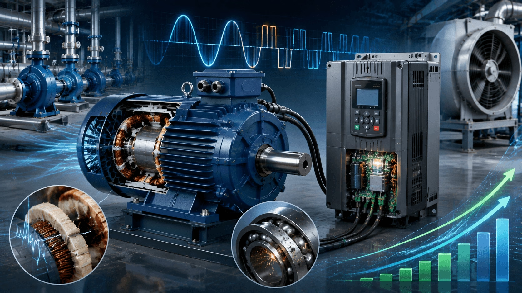
A comprehensive technical guide to VFD-ready motors, encompassing inverter-duty insulation systems, bearing protection technologies, cooling methodologies, PWM waveform effects, and quantifiable energy savings in modern motor systems. Expert engineering insights from Techo Electrical & Mechanical (Titecho).
1. Introduction
Variable Frequency Drives (VFDs) have fundamentally transformed the operation of three-phase motors across industrial, commercial, and building automation sectors. By precisely controlling both voltage and frequency supplied to the motor, VFDs enable accurate speed regulation, soft starting capabilities, and substantial energy savings—particularly in variable-torque applications such as pumps, fans, and compressors.
However, not all motors possess equal compatibility with VFD operation. VFD-ready motors are specifically engineered to withstand the unique electrical stresses imposed by inverter power supplies while delivering reliable performance across extended speed ranges. This guide examines the technical principles underlying VFD-motor integration, the critical design features distinguishing VFD-ready motors, and the measurable benefits they deliver within modern power systems.
2. How VFDs Work: The Technical Foundation
2.1 Variable Voltage, Variable Frequency Control
The synchronous speed of an AC motor is determined by the following relationship:
Ns = (120 × f) / P
Where:
- Ns = Synchronous speed (rpm)
- f = Supply frequency (Hz)
- P = Number of poles
A VFD controls motor speed by varying f while maintaining the V/Hz ratio approximately constant to preserve magnetic flux density:
V / f ≈ constant
Below the motor's base frequency (typically 50 or 60 Hz), the VFD reduces both voltage and frequency proportionally. Above base frequency, voltage remains constant while frequency increases, entering the field-weakening region where available torque declines inversely with speed.
2.2 Power Conversion Stages
A modern VFD comprises three primary stages:
| Stage | Function | Key Components |
|---|---|---|
| Rectifier | Converts AC line input to DC bus voltage | Diode bridge or Active Front-End (IGBT) |
| DC Bus | Filters ripple and stores energy | Capacitor bank; braking chopper (optional) |
| Inverter | Converts DC to variable-frequency AC output | IGBT or SiC MOSFET switches with PWM control |
The inverter stage utilises Pulse Width Modulation (PWM) to synthesise a quasi-sinusoidal output. Modern drives typically switch at 2–16 kHz, with higher frequencies producing smoother current waveforms at the expense of increased switching losses.
2.3 PWM Waveform Characteristics
The PWM output differs fundamentally from sinusoidal grid power in several critical ways:
- Rapid Voltage Transitions: dv/dt can reach 5–10 kV/μs at the motor terminals.
- High-Frequency Harmonics: Switching frequency components and their multiples are superimposed on the fundamental waveform.
- Reflected Waves: Cable inductance and capacitance cause voltage amplification at the motor terminals, potentially doubling the peak voltage relative to the DC bus.
These characteristics generate electrical stresses that standard motors are not designed to withstand over extended service periods.
3. Why Standard Motors Fail on VFDs
Operating a standard grid-designed motor on a VFD exposes it to failure mechanisms absent under sinusoidal supply conditions.
3.1 Insulation Degradation
The steep voltage fronts (high dv/dt) generated by PWM inverters create non-uniform voltage distribution across winding turns. Under sinusoidal supply, voltage distributes evenly; with PWM, the first few turns of a coil can experience 40–80% of the total applied voltage due to inter-turn capacitance effects.
Consequence: Corona discharge and partial discharge activity within the insulation system lead to premature winding failure. Standard motors with Class F insulation may fail within months when operated on VFDs with long cable runs.
3.2 Bearing Damage via Electrical Discharge Machining (EDM)
PWM switching generates common-mode voltage—a high-frequency potential difference between the motor shaft and frame. This voltage charges the shaft capacitively until it exceeds the dielectric strength of the bearing lubricant film (typically 5–15 V/μm), triggering electrical discharge machining:
- Microscopic pits form on bearing raceways and rolling elements.
- Surface degradation accelerates lubricant breakdown.
- Bearing life can be reduced by 80–90% without protective measures.
3.3 Thermal Stress at Reduced Speeds
Standard TEFC motors rely on a shaft-mounted fan for cooling. At reduced speeds, cooling capacity diminishes disproportionately:
| Speed (% Rated) | Cooling Airflow (% Rated) | Thermal Capacity (% Rated) |
|---|---|---|
| 100% | 100% | 100% |
| 75% | 75% | ~85% |
| 50% | 50% | ~65% |
| 25% | 25% | ~40% |
Without independent cooling, a motor operating at 25% speed with 80% load will overheat because cooling capacity has dropped to 40% while I²R losses remain significant.
4. VFD-Ready Motor Design Features
VFD-ready (inverter-duty) motors incorporate specific engineering solutions to mitigate the failure modes described above.
4.1 Reinforced Insulation Systems
| Feature | Standard Motor | VFD-Ready Motor |
|---|---|---|
| Phase-to-ground insulation | Class F (155°C) | Class F or H with enhanced impregnation |
| Turn insulation | Standard enamel | Heavy-build or triple-build inverter-grade enamel |
| Voltage withstand | 1600 V peak | 2000–3000 V peak (per NEMA MG-1 Part 31) |
| Impregnation method | Dip-and-bake | Vacuum Pressure Impregnation (VPI) for void-free insulation |
For critical applications with cable runs exceeding 50 metres, sinewave filters or dV/dt filters installed at the VFD output provide additional insulation protection.
4.2 Bearing Protection Technologies
| Method | Principle | Effectiveness | Relative Cost |
|---|---|---|---|
| Insulated bearings | Breaks electrical circuit through bearing path | High | Medium |
| Shaft grounding ring | Diverts shaft current to ground before reaching bearings | High | Low |
| Insulated bearing housing | Prevents circulating currents entirely | Very High | High |
| Common-mode choke | Reduces common-mode voltage at source | Medium | Medium |
Best Practice: For motors > 100 kW or operating above 480 V, specify insulated bearings on the non-drive end combined with a shaft grounding ring on the drive end.
4.3 Independent Cooling (IC416)
VFD-ready motors intended for constant-torque applications employ separately driven fans (IC416 cooling) rather than shaft-mounted fans (IC411):
- Axial or centrifugal blower powered by an independent constant-speed motor.
- Maintains full cooling capacity regardless of main motor speed.
- Enables continuous operation at 5:1 or 10:1 speed range without thermal derating.
For variable-torque applications (pumps, fans), where load torque decreases with speed, shaft-mounted fans may suffice when applied with appropriate derating curves.
4.4 Speed Range and Torque Capability
| Application Type | Speed Range | Torque Requirement | Cooling Solution |
|---|---|---|---|
| Variable torque (pumps, fans) | 2:1 to 4:1 | Decreases with speed² | Shaft fan often adequate |
| Constant torque (conveyors, mixers) | 10:1 to 1000:1 | Constant across range | Independent fan mandatory |
| Constant power (spindles) | 2:1 to 4:1 (base to max) | Decreases above base speed | Application-dependent |
5. Energy Savings: Quantifying the VFD Advantage
5.1 The Cube Law for Variable-Torque Loads
For centrifugal pumps and fans, power consumption varies with the cube of rotational speed:
P ∝ N³
This relationship yields extraordinary energy savings at part-load conditions:
| Speed (% Rated) | Flow (% Rated) | Power (% Rated) | Energy Savings vs. Throttling |
|---|---|---|---|
| 100% | 100% | 100% | 0% |
| 90% | 90% | 73% | 27% |
| 80% | 80% | 51% | 49% |
| 70% | 70% | 34% | 66% |
| 60% | 60% | 22% | 78% |
| 50% | 50% | 13% | 87% |
Real-World Example: A 75 kW HVAC supply fan operating at 75% average speed for 4,000 hours/year:
- Damper control: ~56 kW average (throttling losses)
- VFD control: ~32 kW average (cubic relationship)
- Annual savings: (56 − 32) kW × 4,000 h × 0.12/kWh = **11,520/year**
5.2 System Efficiency Considerations
Overall system efficiency encompasses the motor, drive, and mechanical transmission:
η_system = η_VFD × η_motor × η_mechanical
Modern VFDs achieve 96–98% efficiency at rated load. Combined with an IE4 motor (96% efficiency) and direct coupling (99%):
η_system = 0.97 × 0.96 × 0.99 ≈ 92%
This compares favourably to throttled systems where the control device (damper or valve) introduces 15–30% additional parasitic losses.
5.3 Payback Analysis
| Investment | Typical Cost | Annual Savings | Simple Payback |
|---|---|---|---|
| VFD retrofit (existing motor) | $300–800/kW | 20–50% of motor energy cost | 1–3 years |
| VFD-ready motor + VFD (new installation) | $400–1000/kW | 25–60% of motor energy cost | 1–2 years |
| Premium efficiency upgrade (IE3→IE4) | +15–30% motor cost | 3–8% energy reduction | 2–4 years |
Critical Factor: Savings depend entirely on the load profile. A motor running at 95% load for 8,000 hours/year benefits far less from VFD control than one operating at variable load with significant part-load hours.
6. Performance Improvements Beyond Energy
6.1 Soft Starting and Mechanical Stress Reduction
VFDs eliminate the high inrush current (5–7× FLA) and torque shock associated with Direct-On-Line (DOL) starting:
| Parameter | DOL Start | VFD Soft Start |
|---|---|---|
| Starting current | 500–700% FLA | 100–150% FLA |
| Starting torque | 150–250% FLT | Adjustable; typically 100–150% FLT |
| Mechanical shock | High (abrupt torque application) | Smooth, programmable acceleration ramp |
| Pipe/duct stress | Water hammer, pressure surges | Gradual pressure build-up |
| Electrical grid impact | Voltage dip, demand charges | Minimal impact |
For large pumping systems, soft starting eliminates water hammer that can damage pipes, valves, and pump casings.
6.2 Precise Process Control
VFDs enable closed-loop control of process variables:
- PID Control: Built into most modern VFDs; automatically adjusts speed to maintain setpoint.
- Multi-Pump Control: VFDs can stage multiple pumps to maintain optimal system efficiency.
- Sleep/Wake Function: Stops motor when demand is minimal; restarts automatically upon demand recovery.
6.3 Power Factor Correction
VFDs with Active Front-End (AFE) topologies or diode rectifiers with DC bus capacitors present near-unity power factor to the supply:
| Configuration | Line Power Factor |
|---|---|
| DOL induction motor | 0.80–0.90 (lagging) |
| VFD with diode rectifier | 0.95–0.98 (lagging) |
| VFD with AFE (Active Front-End) | 0.99+ (unity; regenerative capable) |
This eliminates utility power factor penalties and reduces required transformer and switchgear capacity.
7. Specifying VFD-Ready Motors: Engineering Checklist
When procuring motors for VFD operation, specify the following parameters:
| Requirement | Specification Detail |
|---|---|
| Insulation class | Inverter-duty; 2000 V peak minimum (3000 V for >480 V or long cables) |
| Bearing protection | Insulated NDE bearing + shaft grounding ring for >100 kW |
| Cooling method | IC416 (separate fan) for constant-torque; IC411 with derating curves for variable-torque |
| Speed range | Confirm continuous operation range (e.g., 5:1, 10:1, 100:1) |
| Torque capability | Specify breakdown torque at minimum speed for constant-torque applications |
| Thermal protection | PTC thermistors or PT100 RTDs embedded in windings |
| VFD compatibility | Confirm manufacturer-tested combinations; note switching frequency requirements |
| Cable length | Specify maximum cable run; consider output filters if >50–100 m |
8. Emerging Trends: Wide Bandgap Semiconductors and Smart Drives
8.1 Silicon Carbide (SiC) and Gallium Nitride (GaN)
Wide bandgap semiconductor switches enable transformative improvements:
- Higher switching frequencies: 20–100 kHz versus 2–16 kHz for silicon IGBTs.
- Lower switching losses: Smaller heatsinks, higher power density packaging.
- Smoother motor current: Reduced torque ripple and acoustic noise emission.
- Reduced filter requirements: Lower dv/dt achievable without external filtering components.
8.2 Integrated Motor-Drive Systems
- Smart Motors: VFD electronics integrated directly into the motor terminal box or frame.
- IoT Connectivity: Cloud-based monitoring and predictive maintenance algorithms.
- Digital Twins: Real-time performance optimisation based on actual load profiles.
8.3 Regenerative Drive Capabilities
Active Front-End VFDs return braking energy to the electrical grid:
- Crane and hoist applications: Recover potential energy during load lowering.
- Centrifuges: Regenerate energy during deceleration cycles.
- Test stands: Return test article kinetic energy to facility power system.
9. Conclusion
VFD-ready motors represent the convergence of advanced power electronics and precision electromechanical engineering, enabling levels of efficiency, control, and reliability unattainable with fixed-speed operation. The fundamental engineering insight is that VFD operation imposes unique electrical stresses—steep voltage fronts, bearing currents, and thermal challenges at reduced speeds—that standard motors cannot sustain indefinitely. VFD-ready designs address these challenges through reinforced insulation systems, comprehensive bearing protection, and independent cooling architectures.
For engineers and facility managers, the economic case is compelling: in variable-load applications, VFD systems routinely deliver 20–60% energy savings with payback periods of 1–3 years. When combined with premium efficiency motors (IE4/IE5) and proper system-level design, the total cost of ownership advantage becomes overwhelming. As wide-bandgap semiconductors and integrated smart drive technologies mature, the performance gap between VFD-controlled and fixed-speed systems will continue to widen, making VFD-ready specification the definitive default choice for modern motor applications.
Reference Standards:
- NEMA MG-1 Part 31: Definite-purpose inverter-fed polyphase motors
- IEC 60034-17: Cage induction motors fed from converters
- IEC 60034-25: Guidance for the design and performance of AC motors specifically designed for converter supply
10. Advanced VFD-Ready Motor Solutions with Titecho
Techo Electrical & Mechanical (Taizhou) Co., Ltd. (Brand: Titecho) specialises in the design and manufacture of premium VFD-ready three-phase AC motors engineered for demanding variable-speed applications. Our product portfolio features reinforced inverter-duty insulation systems, comprehensive bearing protection technologies, IC416 independent cooling options, and IE4/IE5 efficiency classifications tailored for seamless integration with modern drive systems.
We provide complete engineering support, including VFD-motor compatibility verification, cable length assessment, filter selection guidance, and system-level energy savings analysis to ensure optimal performance and long-term reliability.
Explore technical data sheets, performance curves, and application engineering support at www.cntecho.com.
© Techo Electrical & Mechanical (Titecho) – Precision Electromechanical Engineering for Intelligent Motion Control