Introduction
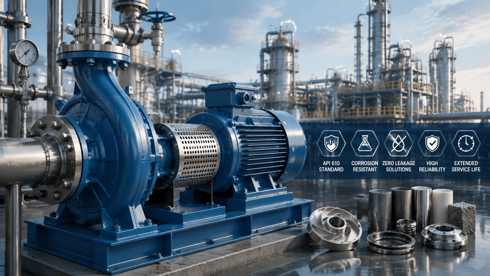
Chemical centrifugal pumps operate at the intersection of fluid mechanics, materials science, and process safety. Unlike clean water or sewage pumps, chemical process pumps must contain aggressive fluids—corrosive acids, toxic hydrocarbons, cryogenic liquids, and superheated reactants—while maintaining zero leakage, surviving thermal cycling, and delivering decades of reliable service under API 610 requirements.
This guide provides a technical treatment of chemical centrifugal pump engineering, including API pump types, seal technology, material selection, NPSH analysis, vibration standards, bearing life prediction, and lifecycle cost optimization. It is designed for process engineers, reliability specialists, and procurement professionals in the chemical, petrochemical, and pharmaceutical industries.
1. What Defines a Chemical Centrifugal Pump?
A chemical centrifugal pump is distinguished not by its hydraulic principle, but by its design standards, material specifications, and containment philosophy.
| Feature | Clean Water Pump | Chemical Process Pump |
|---|---|---|
| Design Standard | ISO 2858 / EN 733 | API 610 / ISO 13709 |
| Pressure Rating | Typically ≤ 16 bar | Up to 200+ bar (BB2/BB5) |
| Temperature Range | -20°C to +90°C | -200°C to +450°C |
| Material Options | Cast iron, bronze, SS 316 | Carbon steel to Hastelloy, Titanium, Duplex |
| Seal Philosophy | Single mechanical seal standard | API 682 seal plans; Sealless for hazardous fluids |
| Shaft Design | Standard deflection limits | Max 0.05 mm at seal face (API 610) |
| Bearing Life | 16,000 hours (L10) | 25,000 h min; 40,000 h target |
| Testing | Hydraulic performance test | Performance + NPSH + Mechanical run + Optional complete unit test |
2. API 610 Pump Types and Applications
The API 610 Standard (12th Edition) is the global benchmark for heavy-duty chemical process pumps. Pump types are defined by shaft orientation and bearing arrangement.
2.1 Pump Type Selection Matrix
| Pump Type | Design Std | Max Flow (m³/h) | Max Head (m) | Max Temp (°C) | Max Press. (bar) | Best Application | Rel. Cost |
|---|---|---|---|---|---|---|---|
| OH2 (Overhung) | API 610 | 2,000 | 300 | 450 | 80 | General process, hydrocarbons | 1.0 |
| BB1 (Axially Split) | API 610 | 30,000 | 250 | 200 | 50 | Large water transfer, pipeline | 1.5–2.0 |
| BB2 (Radially Split) | API 610 | 5,000 | 1,200 | 450 | 200 | High-pressure, critical service | 1.8–2.5 |
| VS4 (Vert. Suspended) | API 610 | 1,500 | 300 | 400 | 60 | Sump, tank farm, deep well | 1.3–1.8 |
| VS6 (Vertical Can) | API 610 | 2,500 | 800 | 350 | 100 | Submerged, cryogenic, LPG | 2.0–3.0 |
| Mag Drive (Sealless) | API 685 | 400 | 150 | 400 | 40 | Toxic, hazardous, zero emission | 2.5–4.0 |
| Canned Motor | API 685 | 200 | 120 | 350 | 60 | Ultra-toxic, nuclear, pharma | 3.0–5.0 |
| Lined (PTFE/PFA) | ISO 2858 | 300 | 80 | 180 | 16 | Corrosive acids, high purity | 1.2–1.8 |
2.2 Selection Decision Criteria
- Flow Rate: Determines OH vs. BB vs. VS architecture.
- Temperature: Dictates centerline mounting (T > 175°C) and cooling requirements.
- Pressure: Selects between axially split (BB1) and radially split (BB2) casings.
- Hazard Classification: Determines seal vs. sealless technology based on toxicity and flammability.
3. Seal Technology: The Critical Containment Decision
Mechanical seals are the most failure-prone component in chemical pumps and the most critical for safety compliance.
3.1 Seal Technology Comparison
| Technology | Leakage Control | Initial Cost | Maint. Ease | Temp. Limit | Solids Tolerance | Service Life | Energy Eff. |
|---|---|---|---|---|---|---|---|
| Single Mech. Seal | Medium | Low | High | Medium | Medium | Medium | High |
| Dual Seal (Pressurized) | High | Medium | Medium | High | High | High | Medium |
| Magnetic Drive | Zero | High | Medium | Medium | Low | High | Low |
| Canned Motor | Zero | Very High | Low | Medium | Very Low | Very High | Low |
| Dry Gas Seal | Very High | High | Low | Very High | Low | Very High | Very High |
3.2 API 682 Seal Plan Quick Reference
| Plan | Description | Typical Application |
|---|---|---|
| Plan 11 | Recirculation from discharge through orifice to seal | General service, clean fluids |
| Plan 21 | Discharge recirculation through cooler to seal | Hot service (> 80°C) |
| Plan 23 | Circulation from seal chamber through cooler | Very hot service, optimal cooling |
| Plan 32 | External flush into seal chamber | Dirty, polymerizing, crystallizing fluids |
| Plan 52 | Unpressurized dual seal with buffer fluid | Moderate hazard, environmental control |
| Plan 53A/B/C | Pressurized dual seal with barrier fluid | Hazardous, toxic, volatile fluids |
| Plan 62 | Quench from external source | Crystallizing, coking, icing prevention |
| Plan 74 | Gas barrier system | Dry gas seals, non-contacting faces |
3.3 Sealless Pump Technology
When zero leakage is mandatory (e.g., phosgene, benzene, EPA MACT compliance):
- Magnetic Drive Pumps: Torque transmitted via magnetic coupling through a containment shell (Hastelloy C/Titanium). Efficiency penalty: 5–15%. Max temp: 400°C. Max power: ~400 kW.
- Canned Motor Pumps: Rotor runs inside process fluid; stator separated by thin can. No external seals. Efficiency penalty: 10–20%. Max temp: 350°C. Preferred for nuclear/pharma/ultra-pure service.
4. Material Selection for Chemical Resistance
Material selection is dictated by corrosion rate, not strength.
4.1 Chemical Resistance Matrix
| Material | H₂SO₄ | HCl | NaOH | HNO₃ | Hydrocarbons | Cl⁻ (>1k ppm) | Max Temp (°C) |
|---|---|---|---|---|---|---|---|
| Carbon Steel (A105) | Poor | Poor | Fair | Poor | Excellent | Poor | 450 |
| SS 316L (CF8M) | Good (<50%) | Poor | Excellent | Good | Excellent | Fair | 450 |
| Alloy 20 (CN7M) | Excellent | Good (<20%) | Excellent | Excellent | Excellent | Good | 400 |
| Hastelloy C-276 | Excellent | Excellent | Excellent | Good | Excellent | Excellent | 1,100 |
| Titanium (Gr.2) | Excellent | Excellent | Poor | Excellent | Excellent | Excellent | 300 |
| Duplex 2205 | Fair | Poor | Good | Good | Excellent | Excellent | 300 |
| PTFE Lined | Excellent | Excellent | Good | Excellent | Poor | Excellent | 180 |
| PFA Lined | Excellent | Excellent | Good | Excellent | Poor | Excellent | 260 |
4.2 Material Selection Logic Tree
- Is fluid strongly acidic (pH < 2)?
- Sulfuric Acid: <50% → SS 316L; >50% → Alloy 20 / Hastelloy.
- Hydrochloric Acid: → Titanium or Hastelloy C-276.
- Other Acids: → Hastelloy C-276 or Inconel 625.
- Is fluid strongly alkaline (pH > 12)?
- T > 80°C → Nickel alloys (Monel, Inconel).
- T < 80°C → SS 316L acceptable.
- Chloride Content?
-
200 ppm → Duplex 2205 minimum.
-
1,000 ppm → Super Duplex or Hastelloy.
-
- Non-corrosive/Mild Duty: Carbon steel or SS 304/316.
5. Temperature-Pressure Ratings and Design Margins
5.1 Common Process Conditions vs. Material
| Process Condition | Temp (°C) | Press. (bar) | Required Material |
|---|---|---|---|
| Crude Oil Distillation | 280 | 25 | Carbon Steel + SS 316 Trim |
| Ethylene Cracker Quench | 85 | 12 | SS 316 or Alloy 20 |
| Hydrocracker Feed | 420 | 180 | SS 316 or SS 347H |
| Sulfuric Acid Transfer | 40 | 6 | Alloy 20 or Hastelloy B |
| Cryogenic LNG | -162 | 8 | Al, SS 304 (Impact Tested), 9% Ni |
| Ammonia Synthesis | 200 | 220 | Carbon Steel (NACE MR0175) |
5.2 Design Margin Rules
| Parameter | Normal Design | Critical / Cyclic Service | Catastrophic Risk |
|---|---|---|---|
| Wall Thickness | 1.5× MAWP | 1.7× MAWP | 2.0× MAWP |
| Allowable Stress | 80% Yield | 67% Yield | 50% Yield |
| Thermal Shock ΔT | 50°C/min | 30°C/min | 15°C/min |
| Shaft Deflection | < 0.05 mm | < 0.03 mm | < 0.02 mm |
| Bearing L10 Life | 25,000 h | 40,000 h | 60,000 h |
6. NPSH and Flashing in Chemical Service
6.1 NPSH Requirements by Fluid
| Fluid | NPSHr (m) | Margin (m) | Total NPSHa Req. (m) | Note |
|---|---|---|---|---|
| Water @ 20°C | 3.5 | 1.0 | 4.5 | Baseline |
| Light Hydrocarbon | 2.8 | 2.0 | 4.8 | Flash risk; low density |
| Propane @ -42°C | 2.2 | 3.0 | 5.2 | Cryogenic; insulation critical |
| H₂SO₄ (98%) | 5.5 | 2.0 | 7.5 | High viscosity (SG 1.84) |
| Caustic (50%) | 4.0 | 1.5 | 5.5 | Crystallization risk |
6.2 Key NPSH Rules for Chemical Service
- Hot Water: +1.5 m margin over cold water NPSHr.
- Hydrocarbons: +2.0 m margin (flash risk/composition variation).
- Viscous Fluids (>50 cP): +1.0 m margin (velocity profile distortion).
- Aerated Liquids (>1% gas): +3.0 m margin (gas binding).
- Verification: Always calculate at maximum operating temperature, not design temperature.
7. Vibration Standards and Bearing Life
7.1 ISO 10816-7 Vibration Zones
| Zone | Level | Action Required |
|---|---|---|
| A | Excellent | Newly commissioned; no action |
| B | Acceptable | Unrestricted long-term operation |
| C | Alert | Restricted operation; plan maintenance |
| D | Danger | Shutdown immediately |
Note: For large pumps (>75 kW) on flexible foundations, Zone B upper limit is 7.1 mm/s RMS, significantly lower than the 11.2 mm/s allowed for rigid foundations.
7.2 Bearing Life Prediction
L₁₀ = (C/P)^p × 10⁶ / (60 · n)
- L₁₀: Rated life (hours, 90% reliability)
- C: Dynamic load rating (N)
- P: Equivalent dynamic bearing load (N)
- p: 3 (ball bearings), 10/3 (roller bearings)
- n: Rotational speed (rpm)
Recommendations:
- Standard Duty: Deep-groove ball, C3 clearance, 25k h target.
- High Temp (150–250°C): Angular contact, polyurea grease, 40k h target.
- VFD Duty: Insulated or ceramic hybrid bearings to prevent electrical pitting.
- Cryogenic: Special low-temp grease and thermal contraction clearance.
8. Reliability and Mean Time to Failure (MTTF)
8.1 Failure Mode Distribution
| Failure Mode | % of Failures | Root Cause | Prevention Strategy |
|---|---|---|---|
| Mech. Seal Leakage | 42% | Face wear, dry run, chem. attack | Proper seal plan, barrier fluid, sealless |
| Bearing Failure | 23% | Lube breakdown, contamination | Oil mist, sealed bearings, vibration monitoring |
| Impeller/Casing Corrosion | 15% | Material incompatibility | Correct material selection, corrosion allowance |
| Shaft Deflection/Breakage | 8% | Misalignment, thermal growth | Laser alignment, centerline mount |
| Coupling Failure | 5% | Misalignment, torque spikes | Disc couplings, proper guarding |
| Motor Burnout | 4% | Overload, phase imbalance | Thermal protection, VFD coordination |
9. Energy Efficiency and Lifecycle Cost (LCC)
9.1 LCC Formula
LCC = C_cap + C_inst + Σ[ (C_energy + C_maint + C_seals + C_emission + C_down) / (1+r)^t ]
9.2 20-Year TCO Comparison (Continuous Duty)
| Technology | Initial Cost | 20Y Energy | 20Y Maint. | 20Y Seals | 20Y Emission | Total 20Y TCO |
|---|---|---|---|---|---|---|
| Single Seal (Plan 11) | $25k | $275k | $125k | $150k | $75k | $650,000 |
| Dual Seal (Plan 53A) | $40k | $290k | $90k | $80k | $25k | $525,000 |
| Magnetic Drive | $70k | $310k | $60k | $0 | $0 | $440,000 |
| Canned Motor | $87.5k | $325k | $50k | $0 | $0 | $462,500 |
| Dry Gas Seal | $55k | $260k | $75k | $40k | $10k | $440,000 |
Key Insight: For hazardous fluids, sealless pumps and dry gas seals achieve 30–35% lower 20-year TCO than single mechanical seals, despite higher initial CAPEX.
10. API 610 Hydraulic Performance
10.1 Typical BEP Ranges (at 2,950 rpm)
| Pump Type | BEP Flow (m³/h) | BEP Head (m) | Specific Speed (N_s) | Eff. at BEP |
|---|---|---|---|---|
| OH2 | 50–400 | 40–120 | 500–2,000 | 72–82% |
| BB1 | 300–1,500 | 30–100 | 1,000–3,000 | 78–88% |
| BB2 | 100–600 | 80–250 | 300–1,200 | 68–78% |
| VS4 | 50–300 | 20–80 | 800–2,500 | 65–75% |
| VS6 | 100–500 | 60–200 | 400–1,500 | 70–80% |
10.2 API 610 12th Edition Key Requirements
- Minimum 3-year bearing life (L10h) at rated conditions.
- Shaft deflection < 0.05 mm at seal face under worst-case loads.
- Centerline-mounted casing for T > 175°C.
- Pressure parts ≥ 1.5× MAWP at design temperature.
- Dual-volute/diffuser for N_s > 4,500 to minimize radial thrust.
- Seal chamber dimensions per API 682.
11. TITECHO: Motor Engineering for Chemical Pumps
TITECHO specializes in hollow-shaft motors for direct-coupled high-pressure applications. Our engineering expertise in corrosion resistance, thermal management, and hazardous area certification is directly transferable to chemical process pumps.
11.1 Motor Design Features
- Construction: Cast iron/steel housings (ASTM A48/A216); SS 316/L shaft extensions; Class H insulation (Class B rise).
- Hazardous Area: Ex d (Zone 1), Ex e (Zone 2), Ex t (Zone 21/22); ATEX & IECEx certified.
- Thermal Protection: PTC thermistors (standard), PT100 RTD (optional), space heaters.
- Bearings: SKF/NSK/FAG standard; insulated/ceramic hybrid for VFD; tapered roller for high axial load.
11.2 Customization Options
| Feature | Standard | Optional |
|---|---|---|
| Power | 0.75 – 315 kW | Up to 630 kW |
| Efficiency | IE3 | IE4, IE5 |
| Protection | IP55 | IP56, IP65, IP66, IP67 |
| Cooling | IC411 (TEFC) | IC416, IC418, IC31W |
| Shaft | C45 Carbon Steel | SS 304/316, 17-4PH, Monel K-500 |
| Terminal Box | Cast Iron, Top | SS 316, Side, Dual-entry |
12. Pump Selection Workflow
- Define Process Conditions: Fluid ID, SG, viscosity, temp/pressure range, flow turndown, NPSHa.
- Assess Hazard Level: Toxicity (TLV/IDLH), flammability, reactivity, environmental regs.
- Select Pump Type: Use API 610 decision tree; verify specific speed and material compatibility.
- Select Seal Technology: Single (non-haz), Dual (moderate), Sealless (high haz/toxic), Dry Gas (clean HP).
- Material Selection: Verify corrosion rate < 0.1 mm/y; check impact toughness at MDMT.
- Motor Sizing: P_shaft = (ρ · g · Q · H) / (3.6 × 10⁶ · η); apply 1.15 SF; confirm Ex rating.
- System Integration: Suction velocity < 1.5 m/s (HC); discharge < 3.0 m/s; thermal relief valves.
- LCC Validation: Compare 20-year TCO of sealed vs. sealless options.
13. Frequently Asked Questions
- What is the difference between API 610 and ANSI B73.1 pumps?
- When should I specify a sealless pump vs. a sealed pump?
- How do I prevent corrosion under insulation (CUI)?
- Can I use carbon steel for sulfuric acid service?
- What is the maximum allowable impeller trim for an API 610 pump?
- How often should I replace mechanical seals?
14. Conclusion
Chemical centrifugal pump engineering demands a systems-level approach integrating process conditions, material science, mechanical design, and regulatory compliance. While API 610 provides the framework, successful selection requires addressing site-specific corrosion mechanisms, emission constraints, and reliability targets.
The most critical decisions—seal technology, material selection, and NPSH margin—have consequences measured in safety incidents and environmental releases, not just dollars. Under-specification in any dimension creates latent liability.
Contact TITECHO: For technical consultation on motor selection, hazardous area certification, hollow-shaft configurations, or custom engineering for corrosive/high-temperature applications.
Appendix: Quick Reference Formulas
| Formula | Application |
|---|---|
| H = (P₂ − P₁)/(ρg) + (v₂² − v₁²)/(2g) + (z₂ − z₁) + H_loss | Total Pump Head |
| P_shaft = (ρ · g · Q · H) / (3.6 × 10⁶ · η_pump) | Shaft Power (kW) |
| N_s = (n · √Q) / H^0.75 | Specific Speed (SI) |
| NPSH_a = (P_atm − P_v)/(ρg) + H_s − H_f | NPSH Available |
| L₁₀ = (C/P)^p × 10⁶ / (60 · n) | Bearing L10 Life |
| Q₂/Q₁ = n₂/n₁ ; H₂/H₁ = (n₂/n₁)² ; P₂/P₁ = (n₂/n₁)³ | Affinity Laws |
| H₂/H₁ = (D₂/D₁)² | Impeller Trimming Law |
References
- API Standard 610, 12th Edition — Centrifugal Pumps for Petroleum, Petrochemical and Natural Gas Industries
- API Standard 682, 4th Edition — Pumps—Shaft Sealing Systems for Centrifugal and Rotary Pumps
- API Standard 685, 2nd Edition — Sealless Centrifugal Pumps for Process Service
- ISO 13709:2009 — Centrifugal pumps for petroleum, petrochemical and natural gas industries
- ANSI/HI 9.6.1 — Rotodynamic Pumps—Guideline for NPSH Margin
- ISO 10816-7:2009 — Mechanical vibration—Evaluation of machine vibration
- NACE International — Corrosion Data Survey—Metals Section
- Karassik et al. — Pump Handbook, 4th Edition