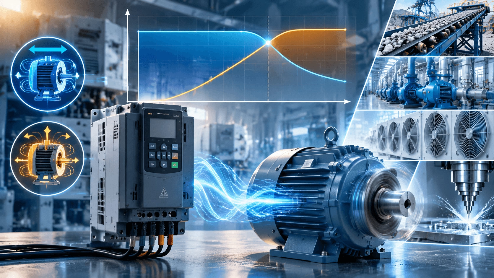
VFD Constant Torque vs. Constant Power 2026: 3-Phase Motor Guide
A definitive technical guide to Variable Frequency Drive (VFD) operating regions in 2026. Master constant torque below base speed and constant power above base speed through field weakening, load matching strategies, and advanced vector control to achieve 30–50% energy savings and optimized system performance.
Unlocking Peak Performance: The 2026 Efficiency Imperative
In the 2026 industrial landscape, characterized by record energy costs, stringent net-zero mandates, and the widespread adoption of IE4/IE5 motors paired with advanced VFDs, understanding the distinction between constant torque and constant power operating regions is no longer optional theoretical knowledge. It is the operational key to reducing energy consumption by 30–50%, extending equipment service life, preventing overload faults, and optimizing processes ranging from heavy conveyors to high-speed CNC spindles.
A persistent engineering error involves oversizing motors, operating inefficiently above base speed, or misdiagnosing torque loss at high RPM as a drive fault. This guide demystifies how modern VFDs intelligently manage voltage, frequency, magnetic flux, and field weakening to deliver precise torque and power profiles tailored to specific application demands. Whether retrofitting legacy systems or designing new automation lines, mastering these electromechanical principles provides a decisive advantage in efficiency, reliability, and return on investment (ROI).
The Fundamental Electromechanical Relationship
All VFD operation is governed by the immutable relationship between mechanical power, torque, and rotational speed:
P = T × ω
Where:
- P = Mechanical Power (kW or HP)
- T = Torque (Nm or lb-ft)
- ω = Rotational Speed (rad/s or RPM, with appropriate conversion constants)
From this relationship, two critical corollaries emerge:
- Doubling speed while maintaining constant torque requires doubling power.
- Doubling speed while maintaining constant power requires halving torque.
VFDs do not create energy; they shape the motor’s operating envelope by precisely controlling the ratio of output voltage (V) to output frequency (f) to maintain stable magnetic flux—or to deliberately reduce flux when entering the constant power region.
Constant Torque vs. Constant Power: Technical Comparison Matrix
| Operating Region | Frequency Range | V/f Ratio | Magnetic Flux | Torque Characteristic | Power Characteristic | Primary VFD Control Action | Typical Applications |
|---|---|---|---|---|---|---|---|
| Constant Torque | 0 Hz → Base Frequency | Constant | Constant (Rated) | Constant (100% Rated) | Increases Linearly with Speed | Maintain Fixed V/f Ratio | Conveyors, positive displacement pumps, mixers, hoists |
| Constant Power | Above Base Frequency | Decreasing | Weakened (Inverse to f) | Decreases Inversely with Speed | Constant (Rated Plateau) | Voltage Clamped; Flux Reduction | Machine tool spindles, winders, centerless grinders |
| Transition Point | At Base Frequency | N/A | Peak Flux | Maximum Continuous Torque | Rated Power Output | Field Weakening Initiation | Design Limit Boundary |
2026 Technical Insight: Modern Sensorless Vector Control (SVC) and Closed-Loop Flux Vector drives maintain full rated torque down to near-zero speed (0.1 Hz) through auto-tuning, slip compensation, and dynamic torque boost algorithms. Traditional scalar V/f control remains viable for general applications but typically requires 10–20% additional torque margin at very low speeds to compensate for stator resistance voltage drop.
Constant Torque Operation: Below Base Speed (0–Base Hz)
The Constant V/f Principle
In the constant torque region, the VFD ramps output voltage and frequency proportionally. For example, a 460V/60Hz motor receives 230V at 30Hz, maintaining a constant V/f ratio of approximately 7.67 V/Hz. This proportional relationship keeps the air-gap magnetic flux constant, which is the foundational requirement for constant torque production.
Flux-Torque Relationship
Motor torque is directly proportional to the product of magnetic flux and active current component:
T ∝ Φ × I_q
Where Φ represents magnetic flux and I_q represents the torque-producing current component. By maintaining constant flux through fixed V/f ratio, the motor can produce rated torque at any speed within this region, limited only by thermal capacity and drive current rating.
Low-Speed Compensation Challenges
Below approximately 10–15 Hz, the voltage drop across stator winding resistance becomes significant relative to total applied voltage. Without compensation, effective air-gap flux decreases, causing torque sag. Advanced 2026 VFDs address this through:
- IR Compensation: Automatic voltage boost proportional to measured current
- Torque Boost: User-adjustable low-frequency voltage enhancement
- Vector Control: Decoupled flux and torque current regulation eliminating V/f limitations entirely
Practical Outcome
Full rated torque (with 150% short-term overload capability) is available continuously from near-zero speed to base speed. Power output scales linearly: at 50% base speed, power output equals 50% of rated power.
Real-World Validation: A wastewater pump operating at 40% speed under constant torque load achieves approximately 60% energy savings compared to fixed-speed operation with throttling valves, with typical payback periods under 18 months.
Field Weakening: Entering Constant Power Above Base Speed
The Voltage Ceiling Constraint
When output frequency exceeds the motor’s base frequency (e.g., >60 Hz for a 60Hz-rated motor), the VFD reaches its maximum output voltage limit—typically equal to supply line voltage. Further frequency increase cannot be accompanied by proportional voltage increase without risking insulation breakdown or exceeding drive semiconductor ratings.
Flux Reduction Mechanism
With voltage clamped at maximum while frequency continues rising, the V/f ratio necessarily decreases. Since magnetic flux is proportional to V/f, flux weakens inversely with frequency:
Φ ∝ V_max / f
Torque-Power Trade-off
As flux decreases, maximum available torque drops inversely with frequency:
T_max ≈ 1 / f
However, since speed increases proportionally with frequency, the product of torque and speed remains approximately constant:
P = T_decreasing × ω_increasing ≈ Constant
This defines the constant power region: rated power output is maintained while torque capability diminishes hyperbolically.
Typical Operating Curves (Standard 4-Pole IE4 Motor)
- 0–60 Hz: Flat torque curve at 100% rated; power rises linearly to 100%.
- 60–120 Hz: Torque declines to ~50%; power plateaus at 100%.
- >120 Hz: Torque continues declining; power may decrease due to increasing core losses, friction, and windage.
2026 Extended Range Capabilities
Modern IE4/IE5 motors with enhanced insulation systems, optimized cooling, and precision bearings can sustain constant power operation up to 2.5–4× base speed. Always verify:
- Nameplate maximum safe frequency rating
- Bearing type and lubrication limits for extended speed operation
- Mechanical balance grade suitable for high-RPM operation
- VFD carrier frequency settings to minimize bearing currents at elevated speeds
Load Type Classification and VFD Region Matching
Correct application requires matching load characteristics to appropriate VFD operating regions:
Constant Torque Loads
- Characteristic: Torque demand independent of speed
- Primary Operating Region: Constant torque (0–base Hz)
- VFD Requirement: Must handle 150% overload at low speed; vector control recommended
- Examples: Positive displacement pumps, belt conveyors, reciprocating compressors, extruders, hoists
Variable Torque Loads
- Characteristic: Torque demand proportional to speed squared (T ∝ n²)
- Primary Operating Region: Typically below base speed; constant power region rarely utilized
- VFD Requirement: Standard V/f often sufficient; energy optimization mode yields additional savings
- Examples: Centrifugal pumps, axial fans, blowers
Constant Power Loads
- Characteristic: Power demand constant; torque decreases inversely with speed
- Primary Operating Region: Deliberately exploits field weakening above base speed
- VFD Requirement: Precise field weakening control; closed-loop feedback preferred
- Examples: Machine tool spindles, film/paper winders, centerless grinders, test stands
⚠️ Critical Warning: Operating a constant torque load (e.g., mixer, conveyor) above base speed without proper derating will result in insufficient torque, causing process stalls, drive overload trips, or motor damage. Always verify load torque requirements across the entire intended speed range.
Advanced 2026 VFD Features Enhancing Performance
Vector Control and Direct Torque Control (DTC)
Provide near-constant torque capability down to standstill, precise torque limiting for tension control, and dynamic response superior to scalar V/f methods. Enable full performance exploitation in both constant torque and constant power regions.
Adaptive Energy Optimization
Automatically adjusts V/f ratio based on real-time load measurement, reducing magnetizing current during partial-load operation. Yields additional 5–15% energy savings beyond baseline VFD efficiency, particularly beneficial for variable torque applications.
Regenerative Braking and Active Front Ends
Recover kinetic energy from overhauling loads (descending elevators, decelerating centrifuges) back to the AC supply rather than dissipating as heat. Essential for high-duty-cycle applications and net-zero compliance.
IoT-Enabled Predictive Monitoring
Cloud-connected dashboards stream real-time torque, power, current, and temperature data. Enable trend analysis, anomaly detection, and predictive maintenance scheduling based on actual operating profiles rather than calendar intervals.
Quantified Benefits and ROI in 2026
| Benefit Category | Typical Achievement | Business Impact |
|---|---|---|
| Energy Savings | 20–60% vs. DOL or mechanical throttling | Direct OPEX reduction; carbon scope 2 emissions reduction |
| Process Precision | ±0.5% speed accuracy; ±3% torque accuracy | Improved product quality; reduced scrap/rework |
| Equipment Longevity | Soft start eliminates inrush; matched torque profiles reduce mechanical stress | Extended bearing/winding life; reduced unplanned downtime |
| Regulatory Compliance | IE4/IE5 + VFD meets EU Ecodesign, DOE 2027, ESG reporting | Avoided penalties; market access; investor confidence |
| Investment Recovery | 6–24 months typical payback on retrofits | Rapid capital recovery; improved cash flow |
Strategic Implementation Guidance
To maximize value from VFD constant torque and constant power capabilities in 2026:
- Profile Your Load First: Measure actual torque-speed requirements across the full operating range before specifying equipment. Assumptions are the enemy of optimization.
- Select Motor for Entire Speed Range: Verify thermal capacity at lowest continuous operating speed and mechanical integrity at highest intended speed. Standard motors may require forced ventilation for sustained low-speed constant torque operation.
- Match VFD Control Mode to Application: Scalar V/f for simple variable torque loads; sensorless vector for demanding constant torque; closed-loop vector for precision constant power applications.
- Commission Thoroughly: Perform auto-tuning, verify torque boost settings, validate field weakening transition point, and establish baseline performance metrics.
- Monitor Continuously: Leverage built-in metering and IoT connectivity to verify actual operation matches design intent and detect degradation early.
Conclusion: Controlled Power Is Intelligent Power
The distinction between average and elite industrial operations in 2026 lies in the intelligent exploitation of VFD operating regions. Wasting energy through mismatched speed-torque profiles, oversized equipment, or uncontrolled field weakening is no longer economically or environmentally defensible.
Pairing premium-efficiency IE3/IE4/IE5 three-phase induction motors with properly configured, application-tuned VFDs transforms electrical power from a commodity expense into a precisely controlled strategic asset. The result is measurable, sustainable competitive advantage.
Optimize Your VFD + Motor System Today
Stop accepting suboptimal performance from mismatched drive-motor-load combinations. Partner with engineers who understand the physics and economics of constant torque and constant power operation.
🌐 Explore Inverter-Duty Motors & Vector-Control VFD Bundles: www.cntecho.com
✉️ Request Free Application Review & Energy Savings Simulation: [email protected]
The smartest power isn’t generated—it’s controlled. Make your system unstoppable.