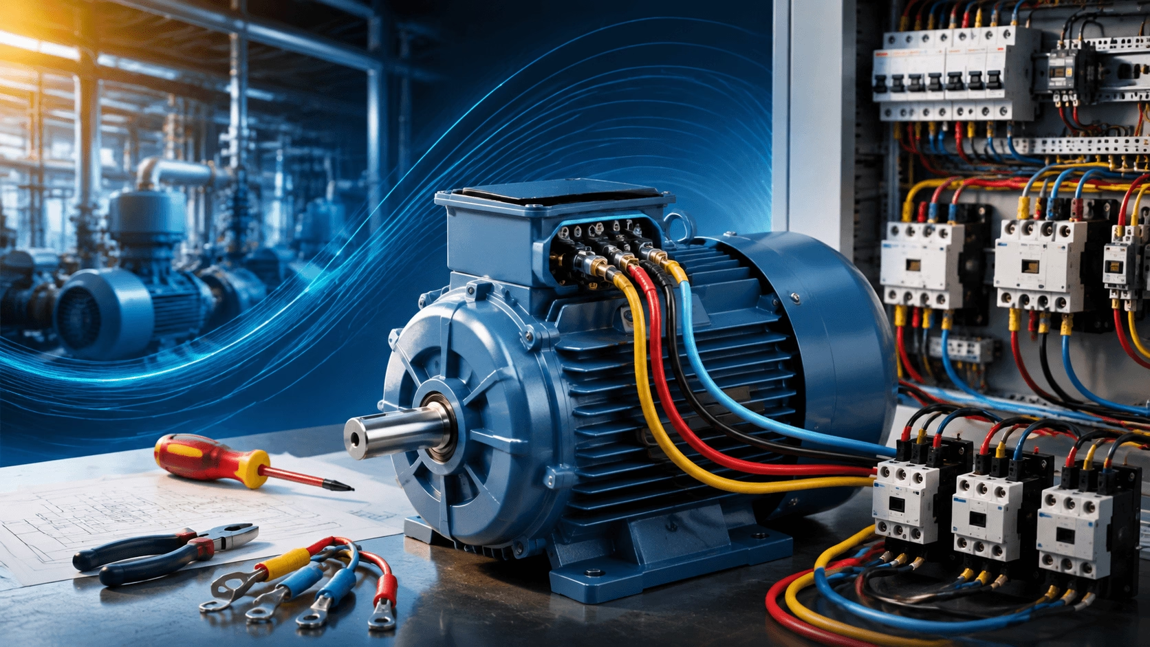
How to Wire a 3-Phase Motor: Star, Delta & Star-Delta Guide 2026
A comprehensive technical guide to connecting three-phase induction motors in Star (Y) or Delta (Δ) configurations. Includes step-by-step wiring procedures, star-delta starter logic, safety protocols, and 2026 best practices for IE3/IE4 efficiency compliance.
Mastering Three-Phase Motor Connections in 2026
Incorrect wiring of a three-phase asynchronous motor is a primary cause of premature failure, characterized by humming, overheating, or failure to start. In the 2026 industrial landscape—defined by rising energy costs, stringent IEC/NEMA compliance, and ubiquitous Variable Frequency Drive (VFD) integration—precision in motor connection is mandatory. It distinguishes reliable 20-year asset performance from costly operational downtime.
Whether installing premium efficiency IE3/IE4 motors, retrofitting legacy equipment, or commissioning new automation lines, correct stator winding configuration is critical. Proper wiring ensures full torque development, mitigates starting current transients, and prevents insulation degradation. This guide provides updated engineering standards, star-delta automation logic, and field-proven troubleshooting methodologies to ensure optimal electromechanical performance.
Fundamental Operating Principles
A three-phase induction motor generates a rotating magnetic field via balanced alternating currents flowing through spatially displaced stator windings. This rotating field induces currents in the rotor (squirrel-cage or wound type), producing torque through electromagnetic interaction. The rotor operates at a speed slightly less than the synchronous speed of the magnetic field; this difference, known as slip, is essential for torque production.
Critical Concept: The stator winding connection topology (Star or Delta) directly determines:
- Voltage stress per phase winding
- Starting current magnitude
- Available starting torque
- Steady-state thermal performance
Star (Y) vs. Delta (Δ) Connections: Technical Comparison
| Feature | Star (Y) Connection | Delta (Δ) Connection | 2026 Application Guidance |
|---|---|---|---|
| Voltage per Winding | Line Voltage / √3 | Full Line Voltage | Use Star for 400V-rated motors on 690V supply |
| Starting Current | ~33% of Direct-On-Line (DOL) | 100% of DOL Current | Use Star to mitigate grid voltage dip and inrush |
| Starting Torque | ~33% of Full-Load Torque | 100% of Full-Load Torque | Use Delta for high-inertia or high-breakaway loads |
| Current Relationship | Line Current = Phase Current | Line Current = √3 × Phase Current | Critical for cable and breaker sizing |
| Thermal Profile | Lower heat generation during start | Higher heat generation | Star-Delta transition optimizes thermal stress for 5.5–75 kW range |
| Typical Applications | Fans, pumps ≤7.5 kW; reduced-voltage starts | Compressors, crushers, conveyors | Match connection to load inertia and grid capacity constraints |
2026 Technical Note: Modern IE4/IE5 motors paired with VFDs typically operate in Delta configuration across the entire speed range. The VFD manages inrush current electronically, often eliminating the need for electromechanical star-delta contactors.
Standard Terminal Markings (IEC 60034 Compliance)
Contemporary three-phase motors adhere to standardized terminal labeling per IEC 60034-8:
- U1, V1, W1: Start terminals of each phase winding
- U2, V2, W2: End terminals of each phase winding
For dual-voltage motors (e.g., 230/400V Δ/Y) or 9-lead configurations, additional links or accessible leads permit rapid reconfiguration. Always verify markings against the manufacturer’s connection diagram before proceeding.
Step-by-Step Wiring Procedures
⚠️ Mandatory Safety Pre-Requisite
Before any electrical work, execute Lockout/Tagout (LOTO) procedures. Verify zero voltage state using a calibrated multimeter or voltage tester rated for the system voltage. Never assume a circuit is de-energized.
Procedure A: Star (Y) Connection
Applicable when nameplate indicates "230/400V Δ/Y" and supply is 400V, or for reduced-voltage starting.
- Verify Isolation: Confirm LOTO and zero voltage.
- Validate Nameplate: Ensure supply voltage matches the Star-rated winding voltage.
- Form Star Point: Connect U2, V2, and W2 together using the provided link bar or jumper wires. This creates the neutral point.
- Connect Supply: Connect L1 → U1, L2 → V1, L3 → W1.
- Ground: Securely connect Protective Earth (PE) to the designated frame ground terminal.
- Torque Verification: Tighten all power terminals to manufacturer specification (typically 2–5 Nm for standard frames). Loose connections are a leading cause of failure.
- Insulation Test: Perform megohmmeter test at 500V DC. Minimum acceptable resistance is >1 MΩ.
- Functional Test: Jog motor briefly to verify smooth rotation and absence of abnormal vibration or noise.
Procedure B: Delta (Δ) Connection
Standard configuration for full-voltage, full-torque operation on matched supply (e.g., 400V motor on 400V supply).
- Verify Isolation: Confirm LOTO and zero voltage.
- Configure Links: Install vertical links between:
- U1 – W2
- V1 – U2
- W1 – V2
- Connect Supply: Connect L1, L2, L3 to the top terminals of the link bridges (U1, V1, W1 respectively).
- Ground: Securely connect PE to frame ground.
- Torque & Inspect: Apply specified torque to all terminals. Visually inspect for proper link seating and conductor integrity.
- Insulation Test: Verify >1 MΩ at 500V DC.
- Operational Validation: Energize and measure phase currents. Balance must be within ±5%.
Rotation Correction: To reverse direction, swap any two line conductors (e.g., L1 and L3). Never attempt reversal while motor is energized.
Star-Delta (Y-Δ) Automatic Starting: 2026 Engineering Standards
For motors typically above 5.5 kW where direct delta starting would cause excessive voltage dip or mechanical shock, star-delta starting remains a widely used electromechanical solution.
Operational Sequence
- Star Start: Motor energized in Y configuration. Winding voltage reduced to Line / √3. Starting current limited to approximately 2–3× rated current (vs. 6–8× for DOL). Starting torque reduced to ~33%.
- Transition Delay: Timer relay maintains Star state for 5–15 seconds (load-dependent) until motor reaches ~80% rated speed.
- Delta Run: Contactor switches to Δ configuration. Full line voltage applied. Motor accelerates to full speed and delivers rated torque.
Critical Design Requirements
- Interlocking: Mechanical and electrical interlocks between Star and Delta contactors are mandatory to prevent catastrophic short circuits.
- Transition Break Time: Incorporate 50–100 ms delay between Star contactor opening and Delta contactor closing to allow arc extinction and prevent transient shorting.
- Overload Protection: Overload relay must be sized for phase current in Delta run mode, not line current.
- 2026 Preference: For new installations, evaluate VFD soft-start capability first. VFDs provide controlled acceleration profiles, eliminate switching transients, and offer superior process control compared to fixed-time star-delta transitions.
Safety Protocols and Best Practices (2026 Non-Negotiables)
- Zero Energy Verification: LOTO is insufficient alone. Always test-before-touch with appropriately rated instruments.
- PPE Compliance: Use 1000V insulated gloves, arc-flash face shields, and FR clothing commensurate with incident energy analysis.
- Precision Torquing: Calibrated torque tools are required. Under-torqued terminals increase resistance, causing localized heating and eventual burnout. Over-torquing damages conductor strands.
- Phase Balance Monitoring: Maintain current balance within ±5% across all phases. Imbalance >10% indicates supply issues, winding faults, or incorrect connections.
- Environmental Protection: Ensure terminal box IP rating matches installation environment. IP55 minimum for general industrial; IP65/IP66 for washdown or outdoor exposure.
- Post-Commissioning Validation: Perform thermographic inspection and vibration analysis after 1 hour of loaded operation to establish baseline and detect anomalies early.
Common Wiring Faults and Field Diagnostics
| Symptom | Probable Cause | 2026 Corrective Action |
|---|---|---|
| Motor hums, fails to start | Single-phasing; incorrect Y/Δ links; blown fuse | Check all fuses, verify link configuration, measure supply voltage at motor terminals under load |
| Rapid overheating | Delta connection on Star-rated windings; overload; blocked ventilation | Recheck nameplate vs. actual connection; verify load current; inspect cooling fan and airflow paths |
| Breaker trips on start | Missing star-delta transition; undersized protection; locked rotor | Verify timer function and contactor sequence; recalculate protection settings; check driven equipment for mechanical binding |
| Excessive vibration/noise | Phase imbalance; loose mounting; misalignment; wrong rotation | Measure phase currents; re-torque mounting bolts; perform laser alignment; verify rotation direction |
| Burnt/discolored terminals | Loose connections; oxidation; undersized conductors | Clean contact surfaces, replace damaged terminals, re-torque to spec, verify conductor ampacity |
Optimizing Performance with IE3/IE4 Motors
Modern high-efficiency motors demand precise installation practices to realize their rated benefits:
- Winding Resistance Sensitivity: IE3/IE4 motors have tighter tolerances; connection errors cause disproportionate efficiency losses.
- Thermal Headroom Reduction: Premium efficiency designs operate closer to thermal limits; correct wiring and cooling are non-negotiable.
- VFD Compatibility: When using VFDs, ensure motor is inverter-duty rated and cables are shielded/symmetrically arranged to prevent bearing currents.
- Documentation: Maintain as-built wiring records and test certificates for future maintenance and compliance audits.
Professional Motor Solutions and Technical Support
For IEC 60034-compliant IE3/IE4 three-phase motors engineered for reliable star, delta, and star-delta operation—with clear terminal markings, robust insulation systems, and comprehensive technical documentation:
🌐 Product Specifications & Wiring Resources: www.cntecho.com
✉️ Request Free Wiring Audit or Custom Specification: [email protected]
Precision wiring. Premium efficiency. Proven reliability.