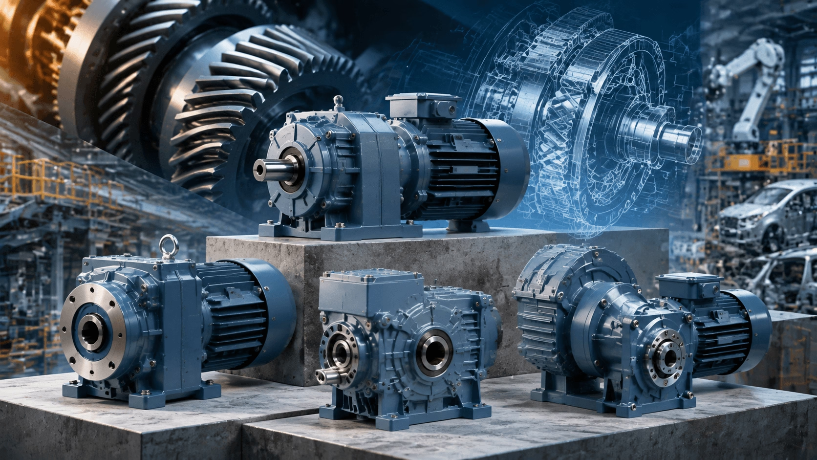
Helical Gear Motor Guide 2026: Types, Advantages & Comparative Analysis
A comprehensive technical reference for helical gear motors in 2026. Covers inline, parallel shaft, and bevel configurations; 95–98% transmission efficiency; noise reduction mechanics; and detailed comparisons against worm and planetary alternatives. Includes application-specific selection criteria, ROI modeling, and smart integration trends for modern industrial power transmission.
The 2026 Industrial Power Transmission Landscape
As manufacturing facilities pursue net-zero targets, scale automation initiatives, and manage escalating energy costs, the helical gear motor has emerged as the dominant solution for critical power transmission applications. Modern helical gear motors—integrating premium IE4/IE5 efficiency motors with precision-ground helical gearing—deliver 95–98% mechanical transmission efficiency, exceptionally low acoustic emissions, high torque density, and service lives exceeding 20 years under continuous 24/7 duty cycles.
These systems are now the standard specification for conveyors, mixers, crushers, robotics, and Automated Guided Vehicles (AGVs) where smooth, reliable, high-load performance is mission-critical. Facilities continuing to operate worm, spur, or legacy helical units typically incur 10–30% energy penalties, elevated noise and vibration levels, and increased maintenance frequency. This guide provides the definitive 2026 technical analysis, including updated comparative data, emerging smart integration capabilities, and quantified return on investment (ROI) methodologies to support specification, upgrade, and lifecycle optimization decisions.
Technical Definition: What Is a Helical Gear Motor?
A helical gear motor is an integrated electromechanical assembly combining an electric motor (three-phase AC induction, permanent magnet synchronous, or servo) with a helical gearbox. The defining characteristic is the helix angle—typically 15° to 30°—at which gear teeth are cut relative to the shaft axis. This geometry enables gradual, multi-tooth engagement rather than the abrupt line contact characteristic of spur gears.
Resulting Performance Characteristics
- Smoother Torque Delivery: Gradual tooth engagement eliminates torque ripple and shock loading.
- Reduced Noise and Vibration: Overlapping contact distributes load and dampens acoustic emissions by 15–20 dB compared to spur equivalents.
- Higher Load Capacity: Simultaneous multi-tooth contact increases effective load-bearing surface area.
- Superior Efficiency: Premium designs achieve up to 98% efficiency per stage through minimized sliding friction.
Unlike spur gears with straight-cut teeth, helical units transmit power between parallel shafts via angled engagement. Variants such as helical-bevel configurations extend this advantage to right-angle power transmission.
2026 System Efficiency Context: With IE4/IE5 motors now standard and VFD pairing ubiquitous, complete helical gear motor systems routinely achieve >90% end-to-end efficiency—a critical parameter for ESG reporting, utility rebate qualification, and regulatory compliance.
Helical Gear Motor Configurations: Selection Matrix
| Type | Shaft Configuration | Key Technical Strengths | Power Range | Primary 2026 Applications | Efficiency Range |
|---|---|---|---|---|---|
| Inline Helical | Coaxial / In-line | Compact envelope, highest efficiency, minimal backlash | 0.09–200 kW | Conveyors, pumps, packaging lines | 95–98% |
| Parallel Shaft Helical | Parallel offset | Flexible mounting options, high torque density, hollow shaft availability | 0.12–250 kW | Mixers, agitators, material handling | 94–97% |
| Helical-Bevel | Right-angle (90°) | Space-saving orthogonal layout, high shock load capacity | 0.12–200 kW | Crushers, rotary tables, cranes, AGVs | 93–97% |
| Helical-Worm Hybrid | Right-angle | High reduction ratios, optional self-locking capability | 0.09–30 kW | Hoists, elevators, back-drive prevention required | 85–92% |
| Customized / Modular | Configurable | Tailored ratios, IP69K washdown, ATEX explosion-proof, IoT-ready | Application-specific | Robotics, food & pharmaceutical (hygienic) | Up to 98% |
2026 Trend Alert: Modular helical-bevel designs featuring quick-change adapters and integrated encoders are dominating new AGV/AMR fleet deployments and smart factory installations, enabling rapid field reconfiguration and closed-loop position feedback.
Operating Mechanics: Engineering Fundamentals
Power Flow Sequence
- Motor Input: Electric motor delivers high-speed rotation to gearbox input shaft.
- Helical Pinion Engagement: First-stage pinion drives mating gear; angled teeth engage progressively across face width.
- Multi-Stage Reduction: Each successive stage multiplies torque while proportionally reducing speed. Overlapping tooth contact distributes load across 2–4 teeth simultaneously.
- Output Delivery: Output shaft provides high torque at reduced RPM with minimal rotational backlash.
- Axial Thrust Management: Helix angle generates axial force component; countered by heavy-duty tapered roller or angular contact bearing arrangements.
Efficiency Advantage Mechanism
Gradual tooth meshing significantly reduces sliding friction compared to worm gear conjugate action. This yields 3–8% higher mechanical efficiency, translating directly to lower operating temperatures, extended lubricant life, and reduced thermal stress on seals and bearings.
Acoustic Performance
The helix angle creates continuous axial overlap in tooth contact, eliminating the impulsive excitation characteristic of spur gear meshing. Measured sound pressure levels are typically 15–20 dB lower than equivalent spur gear units, facilitating compliance with occupational noise exposure regulations without additional acoustic treatment.
Comparative Technology Assessment: Helical vs. Worm vs. Planetary vs. Spur
| Performance Parameter | Helical Gear Motor | Worm Gear Motor | Planetary Gear Motor | Spur Gear Motor |
|---|---|---|---|---|
| Mechanical Efficiency | 94–98% | 50–90% (degrades significantly at high ratios) | 95–98% | 96–99% (but acoustically compromised) |
| Noise / Vibration | Low to Very Low | Moderate | Low | High |
| Torque Density | High | Very High (compact form factor) | Highest | Moderate |
| Backlash | Low (0.5–5 arcmin) | Very Low (self-locking variants) | Very Low (<3 arcmin precision grades) | Moderate to High |
| Axial Thrust Generation | Yes (managed via bearing design) | Minimal | Minimal | None |
| Shock Load Tolerance | Excellent | Good | Outstanding | Fair |
| Relative Cost | Medium–High | Medium | High | Low |
| Optimal Application Profile | Continuous high-load, smooth operation | High ratio, self-locking requirement | Compact high-torque, precision positioning | Low-cost, noise-non-critical |
| 2026 Market Trajectory | Dominant (>46% share) | Declining (efficiency regulations) | Rapid growth (robotics/AMRs) | Niche / low-end legacy |
Strategic Verdict for 2026
- Helical: Wins for balanced performance across the majority of industrial 24/7 continuous-duty applications. Optimal combination of efficiency, durability, cost, and acoustic performance.
- Planetary: Surging adoption in robotics, AMRs, and precision automation where extreme torque density and minimal backlash justify premium cost.
- Worm: Declining except where self-locking functionality is mandatory for safety. Efficiency penalties increasingly disqualify worm gears from new installations under MEPS and corporate sustainability mandates.
- Spur: Largely relegated to cost-sensitive, non-critical applications where noise and vibration are acceptable.
Quantified Advantages in 2026 Operations
Energy Economics
5–15% lower energy consumption versus worm or spur alternatives translates to thousands of dollars in annual savings for medium-to-large facilities. At 0.12/kWh and 6,000 operating hours/year, upgrading a single 15 kW unit from 85% to 96% system efficiency saves approximately **11,880 annually**.
Service Life and Reliability
Properly maintained helical gear motors achieve 20,000–40,000+ hours MTBF. Distributed tooth contact minimizes pitting and wear, while lower operating temperatures preserve lubricant integrity and seal elasticity.
Process Quality
Smooth torque delivery eliminates jerk and vibration artifacts critical in food/pharmaceutical processing, precision packaging, and public infrastructure (airports, escalators, transit systems).
Load Handling Capability
Overlapping multi-tooth contact accommodates variable and shock loads without localized stress concentrations that cause premature failure in spur or worm configurations.
Regulatory Compliance
Acoustic performance meets OSHA, EU Directive 2003/10/EC, and ISO 3744 noise exposure limits without supplementary engineering controls. Compatibility with IE5 motors and VFDs supports net-zero audit documentation and carbon scope 1 & 2 reporting.
Addressing Technical Limitations: Modern Solutions
| Perceived Drawback | 2026 Engineering Solution |
|---|---|
| Axial thrust generation | Premium tapered roller and angular contact bearings are standard; properly sized for continuous axial load at rated torque |
| Higher initial acquisition cost | Typical ROI of 12–36 months via combined energy and maintenance savings; TCO favorable vs. all alternatives in continuous duty |
| Alignment sensitivity | Laser-aligned mounting interfaces and integrated IoT vibration sensors eliminate installation-related failures; predictive alignment monitoring in smart models |
| Thermal management at high speed | Synthetic lubricants (ISO VG 220–320), optimized cooling fin geometry, and optional forced-air or liquid cooling for extreme duty cycles |
Priority Application Sectors for 2026
| Industry Sector | Specific Applications | Critical Performance Requirement |
|---|---|---|
| Material Handling & Logistics | Belt conveyors, sortation systems, AGVs/AMRs | Smooth acceleration/deceleration; precise speed control; high cycle durability |
| Food & Beverage Processing | Mixers, fillers, cappers, hygienic conveyors | Washdown compatibility (IP69K); smooth product handling; FDA-compliant lubricants |
| Mining & Aggregates | Crushers, vibrating screens, apron feeders | Extreme shock load tolerance; dust/seal protection; extended service intervals |
| Automotive & Advanced Manufacturing | Assembly line conveyance, robotic axes, test stands | Precision positioning; high MTBF; seamless VFD/servo integration |
| HVAC & Building Services | Fans, blowers, escalators, moving walks | Low acoustic signature; energy efficiency; 24/7 reliability |
| Renewable Energy | Wind turbine pitch/yaw drives, solar tracker actuators | Environmental sealing; wide temperature range; maintenance accessibility |
Maintenance and Lifecycle Optimization Protocol
Lubrication Management
- Use synthetic ISO VG 220–320 oils specified by manufacturer.
- Oil change interval: 10,000–20,000 operating hours (condition-based with oil analysis preferred).
- Grease-lubricated bearings: Regrease per manufacturer schedule; avoid over-greasing.
Condition Monitoring
- Deploy IIoT vibration and temperature sensors for continuous trending.
- Establish baseline signatures at commissioning; configure alerts for deviation thresholds.
- Perform quarterly axial play checks; document bearing condition.
Installation Precision
- Execute laser alignment during installation. Misalignment accounts for >80% of premature gearbox failures.
- Verify soft foot correction before final torque.
- Confirm proper coupling type and installation per OEM specifications.
Strategic Selection Framework for 2026
- Calculate Load Requirements: Determine output torque (Nm) and speed (RPM) based on actual process demands, not nameplate estimates.
- Apply Appropriate Service Factor: 1.5–2.5 for shock/varying loads; 1.0–1.2 for uniform continuous duty. Undersizing is false economy.
- Specify Mounting and Environmental Protection: Foot, flange, or shaft mount; IP65 minimum for general industrial; IP69K for washdown; ATEX for hazardous areas.
- Prioritize System Efficiency: Specify IE4/IE5 motor paired with ≥96% efficient gearbox. Request certified test data per ISO 14179.
- Evaluate Smart Readiness: For Industry 4.0 integration, require embedded sensors, digital communication protocols (IO-Link, EtherCAT, PROFINET), and cloud-compatible data output.
- Verify Compliance Documentation: CE, UL, CSA, food-grade certifications as applicable to jurisdiction and industry.
Future Trajectory: Smart Helical Gear Motors Beyond 2026
- Embedded Sensing: Real-time torque, load, temperature, and vibration monitoring integrated at factory level; no external sensor installation required.
- AI-Driven Predictive Maintenance: Cloud-based analytics correlate multi-parameter trends to predict remaining useful life (RUL) with >90% accuracy.
- Advanced Materials: Lightweight composites and additive-manufactured components increase power density while reducing inertia and acoustic signature.
- Servo-Class Integration: Seamless VFD + encoder ecosystems deliver positioning accuracy previously exclusive to dedicated servo systems, at helical gear motor price points.
Conclusion: The Strategic Case for Helical Gear Motors in 2026
Helical gear motors represent the optimal intersection of mechanical efficiency, operational reliability, acoustic performance, and economic value for the vast majority of industrial power transmission applications. They are not merely component replacements but strategic enablers of lower total cost of ownership, zero unplanned downtime, and verifiable sustainability compliance.
Continuing to specify or retain worm, spur, or undersized legacy drives in 2026 locks facilities into higher operating costs, regulatory risk, and competitive disadvantage. The transition to premium helical gear technology is both technically justified and economically compelling.
Next-Generation Helical Gear Motor Solutions
For inline, parallel shaft, and helical-bevel gear motors engineered to 2026 performance standards—with IE4/IE5 integration, smart readiness, and comprehensive technical support:
🌐 Product Portfolio & Technical Resources: www.cntecho.com
✉️ Request Free Application Audit, Torque Calculation & ROI Projection: [email protected]
Precision-engineered for 2026. Built for decades of reliable performance.