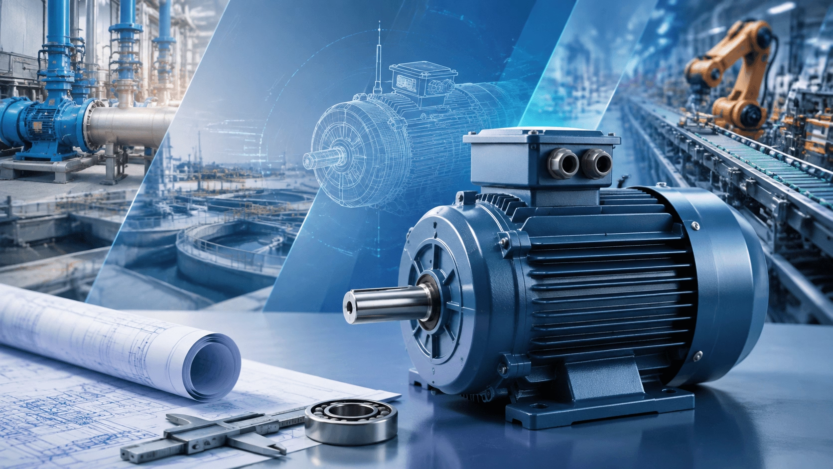
A comprehensive 2026 technical guide for system integrators on specifying three-phase electric motors, encompassing load analysis, IEC standards, efficiency classifications, VFD compatibility, and Total Cost of Ownership (TCO) modelling.
1. Introduction
Within complex engineering projects—ranging from water treatment plants and irrigation systems to industrial automation lines and high-pressure cleaning installations—system integrators bear the critical responsibility of ensuring long-term reliability, energy efficiency, regulatory compliance, and optimal Total Cost of Ownership (TCO).
The three-phase squirrel-cage induction motor remains the dominant prime mover due to its robustness, simplicity, and technological maturity. However, motor selection in 2026 demands a rigorous, multi-disciplinary approach influenced by tightening global efficiency regulations, widespread Variable Frequency Drive (VFD) adoption, and a rising emphasis on lifecycle performance. Poor specification can result in excessive energy consumption (which often constitutes up to 97% of TCO), thermal failures, drive compatibility issues, or non-compliance with updated statutory standards.
This technical guide outlines the professional, step-by-step methodology system integrators apply when specifying three-phase electric motors, incorporating IEC 60034 standards, real-world engineering nuances, edge cases, and 2026 industry trends.
2. Step 1: Detailed Application and Load Analysis
Selection begins with a comprehensive characterisation of the driven load. Integrators must classify loads according to their torque-speed behaviour:
2.1 Load Classifications
- Variable Torque Loads (Quadratic Torque): Centrifugal pumps, fans, and blowers. Power varies with the cube of speed (P ∝ N³). These applications benefit most from VFD control and high-efficiency motors optimised for part-load operation.
- Constant Torque Loads (Linear Torque): Positive displacement pumps, conveyors, mixers, and compressors. These require consistent torque across the speed range and higher starting/breakdown torque capabilities.
- Constant Power Loads: Less common, but relevant in specific machine tools or winding applications.
2.2 Duty Cycle Assessment (IEC 60034-1)
Evaluating the duty cycle is critical for thermal sizing. The IEC standard defines ten duty types:
| Duty Type | Description | Typical Application |
|---|---|---|
| S1 | Continuous Running Duty: Constant load until thermal equilibrium. | Standard pumps, compressors, fans. |
| S2 | Short-Time Duty: Limited duration followed by rest (e.g., 10, 30, 60 min). | Valves, hoists, gate operators. |
| S3 – S6 | Intermittent and periodic duties with varying cyclic duration factors, starts per hour, and inertia ratios (J_L / J_M). | Cranes, presses, automated assembly lines. |
| S7 – S10 | Duties involving electric braking, varying loads/speeds, or discrete constant loads. | Complex automation, traction, test benches. |
Edge Case Consideration: High-inertia systems (e.g., large flywheels or long conveyors) may require reinforced rotor designs or soft-start/VFD solutions to manage inrush currents, which typically reach 6–8× Full Load Amps (FLA) during Direct-On-Line (DOL) starting.
3. Step 2: Power, Speed, Torque, and Frame Size Calculation
The mechanical power requirement is calculated using the fundamental kinematic relationship:
P (kW) = [Torque (Nm) × Speed (rpm)] / 9550
Integrators subsequently select the appropriate pole number (2-pole ≈ 3000 rpm, 4-pole ≈ 1500 rpm, 6-pole ≈ 1000 rpm at 50/60 Hz synchronous speeds) and apply necessary derating factors for:
- Altitude: Elevations >1000 m reduce cooling air density.
- Ambient Temperature: Environments exceeding the standard 40°C baseline.
- Voltage/Frequency Variations: Grid fluctuations of ±5–10%.
- Mounting Configuration: IEC B3 (foot), B5 (flange), B35 (foot and flange), etc. Frame size must ensure mechanical compatibility and adherence to vibration limits (typically ISO 10816).
Note: Oversizing wastes energy and reduces power factor; undersizing risks thermal degradation and reduced lifespan.
4. Step 3: Efficiency Class Selection Aligned with 2026 Regulations
Efficiency remains a primary selection criterion under IEC 60034-30-1. The 2026 regulatory landscape mandates stricter compliance:
| IE Class | Designation | 2026 Regulatory Context & Market Status |
|---|---|---|
| IE3 | Premium Efficiency | The baseline minimum in many global markets. |
| IE4 | Super Premium | Mandatory in the EU for 75–200 kW (since 2023). US DOE requires IE4 for mid-range motors effective June 2027. China GB 18613 emphasises IE3, with IE4 as a reach target. |
| IE5 | Ultra Premium | Gaining rapid adoption for continuous-duty and VFD applications. Offers 10–20% energy reduction versus older designs, particularly at part loads. |
TCO Impact: Energy costs dominate lifecycle expenses (>95%). A 15 kW IE4 motor operating 6,000 hours/year at industrial tariff rates can deliver payback in 12–24 months compared to IE2/IE3 equivalents.
5. Step 4: Environmental Protection, Construction, and Derating
Environmental factors dictate enclosure specifications and material selection:
- IP Rating: IP55 is standard; IP65/IP66 is required for washdown, dusty, or outdoor installations (common in irrigation or high-pressure cleaning).
- Insulation Class: Class F (155°C) with Class B temperature rise is typical; Class H (180°C) is specified for high-temperature environments.
- Cooling Method: IC411 (TEFC) is most common; special methods (IC416 forced ventilation, water-cooled) are utilised for extreme conditions or VFD low-speed operation.
- Corrosion Resistance: Epoxy coatings, stainless steel hardware, or marine-grade finishes are mandatory for humid, coastal, or chemical exposures.
- Hazardous Areas: Explosive atmospheres strictly require ATEX or IECEx certification.
6. Step 5: VFD Compatibility and Drive Integration
Modern engineering projects rarely rely exclusively on DOL starting. Integrators must specify inverter-duty motors equipped with:
- Reinforced Insulation: To withstand high dv/dt voltage spikes and partial discharge inception voltages.
- Bearing Protection: Insulated non-drive end bearings or shaft grounding rings to prevent Electrical Discharge Machining (EDM) currents and bearing fluting.
- Thermal Management: Embedded PTC thermistors or thermostors (e.g., KTY84) coordinated directly with the VFD's overload protection settings.
- Speed Range Capability: Wide constant-torque/constant-power speed ranges without excessive thermal derating.
Best Practice: Match motor FLA to the drive rating, accounting for overload capacity (110–150% depending on torque profile). Consider harmonic mitigation, adherence to recommended cable lead lengths, and carrier frequency optimisation to minimise heating and Electromagnetic Interference (EMI).
7. Step 6: Comprehensive TCO Evaluation and Supplier Qualification
Professional integrators calculate the full lifecycle cost using the following model:
TCO ≈ Acquisition + Installation + Energy (10–15 years) + Maintenance + Downtime + Disposal
Analytical tools incorporate operating hours, load profiles, electricity tariffs, and sensitivity analyses. Qualitative supplier evaluation factors include:
- Global certifications (CE, UL, CCC, etc.).
- Mean Time Between Failures (MTBF) data and acoustic/vibration profiles.
- Spare parts availability and localized technical support.
- Customisation capabilities (special shafts, non-standard flanges, integrated sensors).
In 2026, predictive maintenance features (IoT-ready sensor integration) and compliance with evolving Ecodesign and Minimum Energy Performance Standards (MEPS) add significant strategic value.
8. Application-Specific Examples
| Application | Recommended Motor Specifications |
|---|---|
| Water Pumps & Wastewater | IE4/IE5 efficiency, variable torque profile, IP55+ enclosure, VFD-ready for flow optimisation. |
| High-Pressure Washers & Compressors | Robust constant-torque characteristics, high starting/breakdown torque, reliable S3 intermittent duty performance. |
| Automation & Conveyors | High breakdown torque, precise speed control via VFD, low vibration profiles for alignment longevity. |
9. Titecho: Engineered Solutions for Professional Integration
Techo Electrical & Mechanical (Taizhou) Co., Ltd. (Brand: Titecho) specialises in high-quality three-phase AC induction motors optimised for demanding system integration. Our designs incorporate premium copper windings, IE3/IE4 (and selectable IE5) efficiency classes, robust mechanical construction, and proven inverter-duty performance.
Titecho products are meticulously engineered for water pumps, high-pressure cleaning systems, compressors, and broader industrial applications. We offer flexible mounting configurations, advanced protection ratings, and bespoke customisation options to meet stringent project specifications.
Explore technical data sheets, efficiency curves, and application support at www.cntecho.com.
10. Conclusion: Systematic Selection Ensures Project Success
In 2026, professional motor selection by system integrators is a disciplined process integrating mechanical analysis, IEC 60034 standards, regulatory compliance, drive compatibility, environmental engineering, and rigorous TCO modelling. This systematic approach minimises operational risks, maximises energy savings and uptime, and delivers measurable ROI amid global efficiency mandates and electrification trends.
By partnering with experienced manufacturers early in the design phase, integrators can access tailored solutions that align precisely with project performance guarantees and sustainability goals.
For technical consultations, motor selection support, or custom three-phase motor solutions optimised for your engineering projects, contact the Titecho team through www.cntecho.com. Our expertise in AC motors for pumps and high-pressure systems ensures the delivery of reliable, efficient, and future-proof installations.
© Techo Electrical & Mechanical (Titecho) – Engineering Excellence in Industrial Drive Systems