A Comprehensive Technical Guide to Diagnosing, Preventing, and Resolving Cavitation in Industrial Pumping Systems Through Rigorous Hydraulic Design, Condition Monitoring, and Lifecycle Management
Cavitation remains one of the most insidious and economically damaging phenomena in industrial fluid handling. Despite decades of advancement in hydraulic design, materials science, and predictive diagnostics, cavitation continues to accelerate component degradation, compromise system reliability, and inflate lifecycle operating costs across manufacturing, municipal water, petrochemical, and power generation sectors.
For facility engineers, asset managers, and process operators, understanding the thermodynamic origins of cavitation, recognizing its early diagnostic signatures, and implementing evidence-based mitigation protocols is essential to sustaining optimal pump performance. This guide provides a technically rigorous examination of pump cavitation, integrating fundamental physics, standardized engineering practices per Hydraulic Institute (HI) and API 610 guidelines, field-validated case studies, and actionable mitigation strategies aligned with modern digital monitoring capabilities.
1. The Hydrodynamic and Thermodynamic Mechanism of Cavitation
Phase-Change Physics
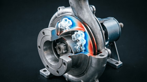
Cavitation is fundamentally a phase-change phenomenon, not merely a mechanical or hydraulic anomaly. It initiates when the local static pressure within a pump’s suction zone or impeller inlet drops below the vapor pressure of the conveyed fluid at its operating temperature. Under these sub-saturation conditions, dissolved gases come out of solution and liquid molecules nucleate into microscopic vapor cavities.
As the fluid accelerates through the impeller passages and encounters rising static pressure toward the discharge side, these vapor bubbles undergo rapid, asymmetric collapse. The implosion process is extraordinarily violent:
- Transient Pressures: Localized microjets and spherical shockwaves generate peak pressures frequently exceeding 1,000 MPa (~145,000 psi).
- Timescale: Individual collapse events occur on the order of microseconds, but their cumulative frequency (thousands per second) induces cyclic fatigue loading.
- Material Response: Repeated high-frequency stress waves exceed the endurance limit of metallic surfaces, causing subsurface crack initiation, grain boundary separation, and progressive material loss.
Distinction from Related Phenomena
Accurate diagnosis requires differentiating true cavitation from visually or acoustically similar anomalies:
| Phenomenon | Root Cause | Key Differentiator |
|---|---|---|
| True Cavitation | Local pressure < vapor pressure | High-frequency broadband acoustic emission; damage on low-pressure surfaces |
| Air Entrainment | External air ingress via leaks/vortices | Discrete bubble presence; noise diminishes with increased backpressure |
| Suction Recirculation | Off-BEP operation causing flow reversal | Vibration at sub-synchronous frequencies; damage on pressure side of vanes |
| Discharge Recirculation | Low-flow operation causing eddies | Damage on volute/diffuser; occurs below minimum continuous stable flow |
| Mechanical Faults | Imbalance, misalignment, bearing wear | Synchronous or non-hydraulic spectral peaks; unaffected by NPSH margin changes |
Critical Insight: Cavitation can coexist with other faults. Systematic elimination of mechanical causes before attributing symptoms to hydraulics prevents misdiagnosis and wasted corrective effort.
Positive Displacement Pump Cavitation
While centrifugal pumps receive primary attention, PD pumps are equally vulnerable but manifest differently:
- Valve Flutter: Inadequate filling causes check valves to chatter, generating impact loads and seat erosion.
- Plunger/Piston Scoring: Vapor collapse in compression chambers creates localized hot spots and lubrication film breakdown.
- Seal Degradation: Pressure pulsations from incomplete chamber filling accelerate face wear and elastomer extrusion.
- Flow Instability: Discharge flow becomes erratic despite constant speed, indicating incomplete volumetric efficiency.
2. Net Positive Suction Head (NPSH): Quantitative Framework and Safety Margins
Fundamental Definitions
The NPSH balance governs cavitation probability and must be rigorously quantified for every installation:
NPSHa = P_atm + P_static - P_vapor - h_friction - h_velocity
Where:
- P_atm = Atmospheric pressure at site elevation (decreases ~1.2 kPa per 100 m altitude)
- P_static = Static head above pump centerline (positive if flooded suction, negative if lift)
- P_vapor = Fluid vapor pressure at actual operating temperature (exponential function of T)
- h_friction = Suction piping friction losses including fittings, valves, strainers
- h_velocity = Velocity head at pump suction flange (v²/2g)
NPSHr = Minimum NPSH required by pump to maintain specified performance (typically defined at 3% head drop per HI 9.6.1). Determined empirically by manufacturer testing; varies with flow rate, speed, and impeller geometry.
Safety Margin Standards
Industry practice has evolved beyond simple additive margins toward ratio-based criteria accounting for scale effects and transient uncertainties:
| Application Category | Recommended Margin | Rationale |
|---|---|---|
| Cold water, clean service | NPSHa ≥ NPSHr + 0.5–1.0 m OR Ratio ≥ 1.3 | Moderate consequence; well-characterized fluid properties |
| Hot water / condensate | Ratio ≥ 1.5–2.0 | Vapor pressure sensitivity to temperature fluctuations; flash risk |
| Hydrocarbons / volatile fluids | Ratio ≥ 2.0–3.0 | Thermodynamic correction factors; dissolved gas release |
| Slurry / abrasive media | Ratio ≥ 2.0 + erosion allowance | Particle-induced nucleation sites; accelerated damage kinetics |
| Critical / unspared assets | Ratio ≥ 2.0 + continuous monitoring | Downtime cost justifies conservative design and real-time verification |
Warning: Manufacturer-published NPSHr values are typically based on cold water testing. For hot hydrocarbons, apply thermodynamic correction factors per API 610 Annex B or HI 9.6.1. Uncorrected values can underestimate required margin by 30–50%.
Dynamic NPSH Considerations
Static calculations assume steady-state conditions. Real systems experience transients that temporarily depress NPSHa:
- Startup/Shutdown Transients: Accelerating columns, valve actuation surges, and level oscillations create momentary NPSH deficits even when steady-state margins appear adequate.
- Process Upsets: Feed tank depletion, heat exchanger fouling, or upstream pump trips alter suction conditions faster than operator response time.
- Seasonal Variations: Summer ambient temperatures elevate fluid vapor pressure; winter viscosity increases friction losses.
- Aging Effects: Pipe scaling, strainer blinding, and internal corrosion progressively increase h_friction over years of service.
Design for worst-case credible transient, not nominal steady state. Implement continuous NPSHa monitoring for critical services where transient risk cannot be eliminated through design alone.
3. Diagnostic Signatures and Advanced Detection Methodologies
Multi-Parameter Correlation Protocol
No single indicator definitively confirms cavitation. Reliable diagnosis requires correlating multiple independent measurements:
Acoustic Emission Monitoring
- Frequency Band: Broadband energy concentrated in 10–100 kHz range distinguishes cavitation from mechanical vibration (<2 kHz).
- Signature Evolution: Early-stage cavitation produces intermittent crackling; developed cavitation generates continuous gravel-like roar; severe cavitation may paradoxically quiet as vapor blanket suppresses discrete collapses (indicating imminent catastrophic failure).
- Sensor Placement: Suction-side casing proximity yields highest signal-to-noise ratio; avoid mounting near bearings or gearbox interfaces.
Vibration Spectral Analysis
- Blade-Pass Frequency (BPF): Elevated amplitude at BPF and harmonics indicates hydraulic excitation.
- Non-Synchronous Peaks: Sub-synchronous or fractional-order peaks suggest recirculation rather than classical cavitation.
- Time-Waveform Characteristics: Random, impulsive transients distinguish cavitation from periodic mechanical faults.
- Load Dependence: Cavitation-induced vibration typically intensifies with flow rate above BEP; recirculation worsens below BEP.
Hydraulic Performance Mapping
- Head-Capacity Curve Deviation: Progressive flattening or instability at high-flow end signals suction cavitation.
- Efficiency Decline: 3–5% efficiency drop often precedes audible noise or visible damage.
- Power Fluctuation: Erratic power draw at constant speed indicates two-phase flow instability.
- Test Protocol: Conduct controlled step-test across operating range while logging head, flow, power, and vibration simultaneously.
Thermal and Process Indicators
- Suction Temperature Spikes: Flash vaporization absorbs latent heat; localized cooling detectable via IR thermography or RTDs.
- Pressure Transducer Noise: High-frequency ripple superimposed on mean suction pressure reading.
- Downstream Quality Issues: Gas binding in downstream vessels, metering inaccuracies, or product contamination.
Digital Twin and Machine Learning Integration
Advanced facilities deploy physics-informed ML models that:
- Establish baseline cavitation-free signatures across operating envelope during commissioning.
- Detect subtle pattern shifts preceding human-perceptible symptoms by weeks or months.
- Correlate NPSH margin trends with maintenance history to predict remaining useful life.
- Recommend operational adjustments (speed reduction, flow throttling, sequencing) to restore safe margins automatically.
4. Field-Documented Case Studies: Verified Engineering Interventions
The following anonymized cases illustrate systematic resolution of cavitation-induced failures using standardized engineering methodologies. All data reflects documented field implementations with verified outcomes.
Case Study 1: Municipal Cooling Water System — Centrifugal Process Pump
Background: A 450 kW end-suction centrifugal pump circulating 85°C cooling water experienced progressive head loss and repeated mechanical seal failures after 14 months of service. Three unplanned shutdowns incurred significant production disruption.
Diagnostic Findings:
- NPSHa calculation revealed margin of only 0.3 m above published NPSHr.
- Suction piping contained three 90° elbows within 2 m of pump inlet, violating HI 9.6.1 straight-run requirements.
- Seasonal summer temperature spikes further depressed NPSHa by 0.4 m.
- Acoustic emission confirmed developed cavitation; vibration showed elevated BPF harmonics.
Engineering Intervention:
- Piping Reconfiguration: Redesigned suction header to provide ≥5D straight run upstream of impeller eye; replaced elbows with long-radius bends and installed flow straightener.
- VFD Integration: Installed variable frequency drive to modulate speed and maintain operation within ±10% of BEP across seasonal load variations.
- Real-Time Monitoring: Integrated differential pressure transmitter and RTD into plant SCADA for continuous NPSHa calculation; automated flow throttling triggered when margin fell below 1.0 m.
- Operational Protocol: Revised SOP prohibiting operation above 110% BEP during peak summer conditions.
Verified Outcomes (18-Month Post-Intervention):
- Cavitation noise eliminated within 72 hours of piping modification.
- Impeller inspection revealed zero pitting or surface degradation.
- Energy consumption decreased by 19% through optimized speed control.
- MTBF extended from 11 months to 34 months; seal replacements reduced from 3/year to scheduled annual PM.
- ROI achieved in 8 months through energy savings and avoided downtime.
Case Study 2: Petrochemical Condensate Transfer — API 610 Overhung Pump
Background: A hot condensate transfer pump operating at 115°C and 4.2 bar suction pressure suffered recurring vane erosion, shaft deflection, and bearing failures. Three emergency shutdowns occurred within a single fiscal year, each costing >USD 180,000 in lost production and expedited repairs.
Diagnostic Findings:
- Flash vaporization occurring due to pressure drop across partially blinded suction strainer (ΔP = 0.8 bar vs. clean ΔP = 0.2 bar).
- Inadequate static submergence in receiving vessel during low-level operations.
- Original AISI 316L impeller showing classic cavitation pitting on leading edges and suction shroud.
- Vibration spectra showed severe BPF excitation with non-synchronous modulation indicating combined cavitation and recirculation.
Engineering Intervention:
- Inducer Retrofit: Installed axial inducer reducing effective NPSHr by 1.2 m, restoring adequate margin under degraded strainer conditions.
- Material Upgrade: Replaced impeller with duplex stainless steel (UNS S31803) featuring Stellite 6 hardfacing on leading edges and suction shroud.
- Hydraulic Stabilization: Installed anti-vortex baffles in suction vessel; raised minimum operating level setpoint by 0.8 m.
- Strainer Management: Implemented differential pressure alarm at 0.4 bar trigger; doubled cleaning frequency during high-fouling periods.
- Condition Monitoring: Permanently mounted AE sensor with trending dashboard integrated into operator HMI.
Verified Outcomes (26-Month Continuous Operation):
- Vibration amplitude at BPF reduced by 68%.
- Annual maintenance expenditure declined by 42%.
- Zero unplanned shutdowns attributable to hydraulic causes.
- Impeller inspection at 24-month interval showed minimal wear; projected replacement interval extended to 5+ years.
- Insurance premium adjustment secured based on demonstrated risk reduction.
Case Study 3: Agricultural Irrigation — Variable-Speed Booster Station
Background: A multi-pump booster station serving drip irrigation network experienced intermittent cavitation during low-demand nighttime cycles. Operators had manually shut down pumps to avoid noise complaints, causing pressure instability and crop stress.
Diagnostic Findings:
- Pumps sized for peak daytime demand operated at <30% BEP during off-peak hours.
- Fixed-speed operation caused suction recirculation and discharge instability at low flows.
- No minimum flow protection or automatic staging logic.
Engineering Intervention:
- VFD-Based Flow Modulation: Implemented closed-loop pressure control with turndown to 25% speed.
- Automatic Staging Logic: PLC-controlled lead/lag sequencing maintaining each active pump within 70–110% BEP.
- Minimum Flow Bypass: Installed automatic recirculation valve opening below 40% BEP threshold.
- Impeller Trimming: Reduced impeller diameter by 8% to better match revised duty envelope.
Verified Outcomes:
- Nighttime cavitation completely eliminated; noise complaints ceased.
- Energy consumption reduced by 31% annually through right-sized operation.
- Crop yield stabilized; farmer revenue increased USD 45,000/year.
- Bearing and seal life doubled due to elimination of off-design operation.
5. Engineering Mitigation and Lifecycle Management Strategies
Tiered Mitigation Hierarchy
Apply interventions in order of effectiveness and cost-efficiency:
Tier 1: System-Level Corrections (Highest Impact)
- Increase static suction head through tank elevation or pressurization.
- Reduce fluid temperature via upstream cooling or insulation.
- Minimize suction line friction through larger diameter, smoother bore, optimized routing, and regular strainer maintenance.
- Eliminate air ingress points; ensure gaskets, seals, and valve packing are leak-tight.
- Install vortex breakers and adequate submergence for sump applications per HI 9.8.
Tier 2: Equipment Selection and Modification
- Specify low-NPSHr impeller designs with larger eye areas, reduced inlet velocities, and optimized blade inlet angles.
- Employ double-suction configurations balancing axial thrust and reducing inlet velocity.
- Install inducers for marginal NPSH applications (accepting slight efficiency penalty for reliability gain).
- Select cavitation-resistant materials: duplex/super-duplex stainless steels, nickel-aluminum bronze, or hardened alloys for severe service.
- Apply protective coatings: thermal-sprayed ceramics, epoxy composites, or laser shock peening (LSP) inducing beneficial compressive residual stresses.
Tier 3: Operational Controls and Protection
- Implement VFD speed control matching demand while maintaining safe NPSH margins.
- Install automatic minimum flow recirculation valves preventing low-flow recirculation damage.
- Program soft-start ramps avoiding acceleration-induced NPSH transients.
- Establish operating envelopes with alarms at NPSH margin thresholds; interlocks for critical excursions.
- Develop startup/shutdown procedures explicitly addressing transient NPSH management.
Tier 4: Predictive Maintenance and Analytics
- Deploy permanent AE/vibration monitoring on critical unspared assets.
- Integrate NPSH margin tracking into DCS/SCADA with historical trending.
- Conduct periodic performance testing to detect efficiency degradation signaling incipient damage.
- Use oil analysis and ferrography to detect early-stage wear particle generation.
- Maintain digital twin models updated with as-operated data for scenario simulation.
Material Selection Guidance by Severity
| Service Severity | Recommended Materials | Surface Treatment | Notes |
|---|---|---|---|
| Mild (cold water, ample margin) | Cast iron, bronze | Standard paint/coating | Cost-optimized; monitor margins |
| Moderate (warm water, tight margin) | 316 SS, CD4MCu | Epoxy composite coating | Balance of cost and resistance |
| Severe (hot condensate, hydrocarbons) | Duplex SS, Ni-Al Bronze | Stellite hardfacing, LSP | Extended life justification |
| Extreme (slurry, high-temp, critical) | Super duplex, titanium, ceramic-lined | Ceramic overlay, LSP | Capital-intensive; reserve for unspared critical assets |
Economic Note: Material upgrades should be justified through TCO analysis comparing incremental capital cost against extended MTBF, reduced downtime, and deferred replacement. Premium materials rarely pay back in spared, non-critical services.
6. Standards Compliance and Documentation Requirements
Applicable Industry Standards
Rigorous cavitation management references authoritative standards:
- HI 9.6.1: Rotodynamic Pumps for NPSH Margin Determination — Primary reference for margin selection and testing methodology.
- HI 9.8: Pump Intake Design — Sump geometry, submergence, and vortex prevention criteria.
- API 610: Centrifugal Pumps for Petroleum, Petrochemical, and Natural Gas Industries — Stringent NPSH, material, and testing requirements for critical hydrocarbon service.
- ISO 9906: Rotodynamic Pump Acceptance Tests — Defines test grades and tolerance bands for NPSHr verification.
- IEC 60034-14: Mechanical Vibration of Rotating Electrical Machines — Vibration severity zones and measurement protocols.
- ASTM G32/G134: Standard Test Methods for Cavitation Erosion Testing — Material ranking and qualification procedures.
Documentation Expectations for Procurement and Audit
Professional buyers and auditors expect comprehensive cavitation-related documentation:
- Certified NPSHr curves across full operating range with test grade notation.
- NPSH margin calculation worksheets showing all assumptions, fluid properties, and safety factors.
- Material certificates and hardness/coating thickness verification for wetted components.
- Factory acceptance test reports including NPSH verification points.
- Installation manuals specifying suction piping requirements, alignment tolerances, and commissioning procedures.
- O&M manuals defining operating envelopes, monitoring parameters, and maintenance intervals tied to cavitation risk.
Suppliers unable or unwilling to provide this documentation should be considered high-risk regardless of quoted price.
7. TECHO Electrical & Mechanical: Cavitation-Aware Engineering Partnership
TECHO Electrical & Mechanical (Taizhou) Co., Ltd. recognizes that cavitation management extends beyond pump supply into systemic engineering partnership. Our approach integrates hydraulic expertise, application-specific validation, and lifecycle support to deliver sustainable cavitation-free operation.
Our Cavitation Competencies
- Low-NPSHr Hydraulic Designs: CFD-optimized impellers and inducer-equipped configurations validated through ISO 9906 Grade 2 testing.
- Application-Specific NPSH Analysis: Site-calculated margin verification accounting for fluid properties, elevation, transients, and aging effects—not generic catalog values.
- Material and Coating Options: Full spectrum from standard cast iron to duplex stainless with hardfacing, matched to service severity and TCO targets.
- Integrated Motor-Pump Matching: Ensuring electromagnetic and hydraulic synergy prevents off-design operation that triggers cavitation.
- Commissioning and Validation Support: On-site or remote assistance with NPSH verification, performance testing, and baseline condition monitoring setup.
- Documentation Excellence: Complete technical packages meeting HI, API, and ISO standards; responsive to audit and regulatory inquiries.
Request Cavitation Risk Assessment
Submit your application parameters and receive a complimentary preliminary cavitation risk evaluation including NPSH margin assessment, recommended mitigation tier, and estimated TCO impact of proposed solutions. Our engineering team stands ready to support new installations, troubleshoot existing problems, or validate third-party designs.
Visit www.cntecho.com to access NPSH calculation templates, request technical consultation, or download our comprehensive Cavitation Prevention Handbook.
Disclaimer: This guide provides general engineering information and does not constitute site-specific design advice. Cavitation behavior depends on complex interactions between fluid properties, system configuration, equipment design, and operational practices. Always conduct detailed engineering analysis qualified to your specific application. Case study results reflect documented field implementations but individual outcomes may vary. Consult qualified fluid handling professionals for critical decisions.