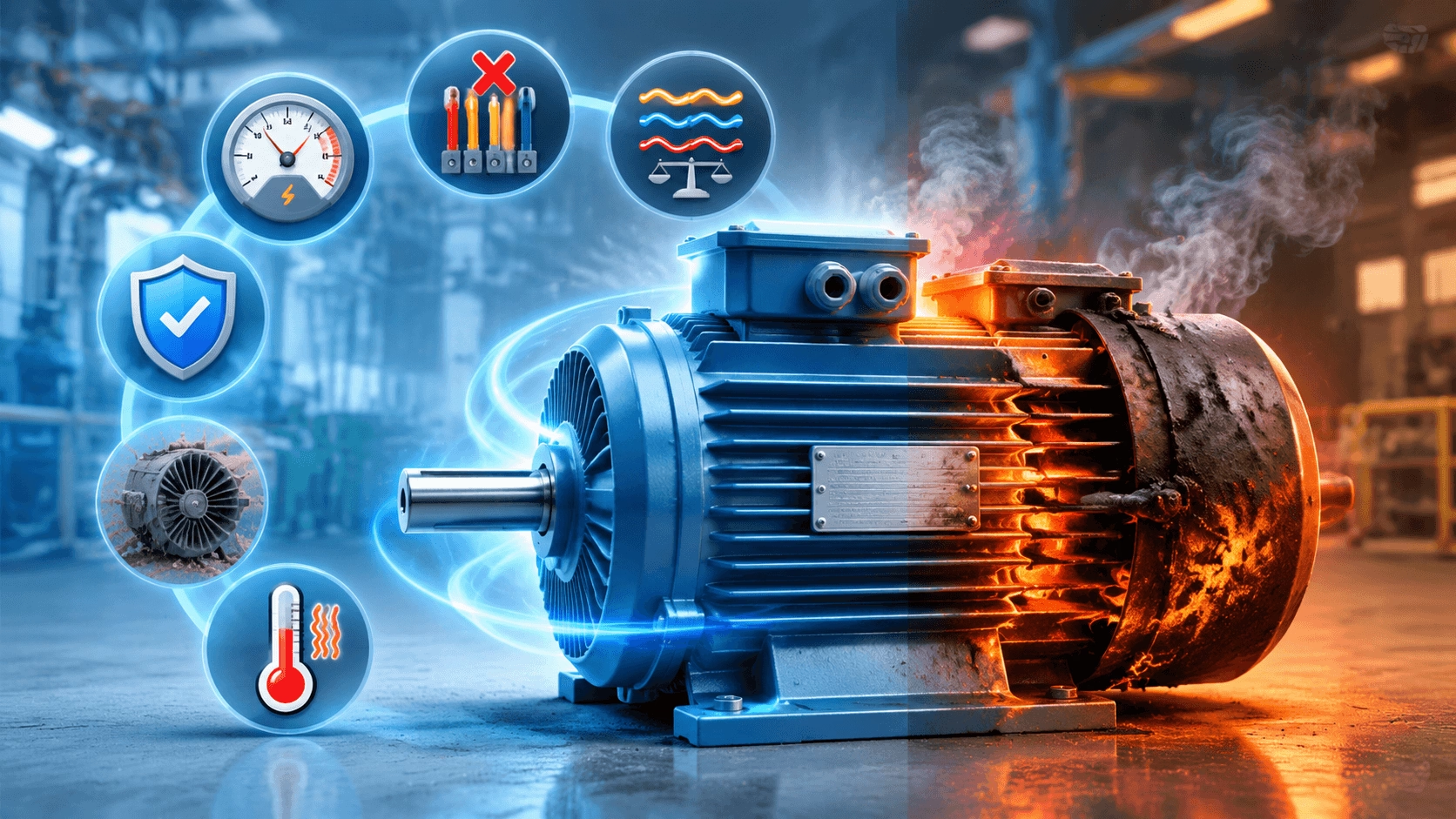
2026 Industrial Reliability Guide: A comprehensive engineering analysis of the top 10 causes of three-phase induction motor failure. Covers overload dynamics, phase loss physics, voltage imbalance impacts, harmonic distortion from VFDs, and actionable prevention strategies to minimize downtime and extend asset life. Compiled with TITECHO industrial expertise.
Introduction: The High Cost of Motor Failure
Three-phase induction motors are the unsung heroes of modern industry, powering manufacturing lines, water treatment plants, HVAC systems, compressors, and conveyor networks with remarkable reliability. They operate tirelessly, often in harsh environments, for years without issue. However, when a motor fails, it is rarely a sudden, random event. It is almost always the culmination of underlying stressors that have been ignored.
A single motor burnout can halt an entire production line, leading to thousands of dollars in lost revenue, emergency repair costs, and expedited shipping fees for replacement parts. Understanding the root causes of motor burnout is not just about fixing a broken machine; it is about implementing a proactive maintenance strategy that extends equipment life, reduces energy waste, and ensures operational continuity.
This guide breaks down the 10 most common reasons three-phase motors overheat and fail, explains the early warning signs you should never ignore, and provides actionable, engineering-grade prevention strategies tailored to the 2026 industrial landscape.
Quick Refresher: How a Three-Phase Motor Works
To understand why motors fail, one must first understand how they succeed. A three-phase induction motor uses three alternating currents, offset by 120 electrical degrees, to create a smooth Rotating Magnetic Field (RMF) in the stator. This field induces current in the rotor conductors, generating torque without any physical contact between the stator and rotor. This non-contact design is why these motors are so durable.
However, this system is sensitive. Any disruption to the voltage balance, current flow, cooling efficiency, or mechanical load can cause excessive heat buildup. Heat is the enemy of insulation. When winding temperatures exceed their thermal class limits (e.g., 155°C for Class F), the insulation begins to degrade, leading to short circuits, ground faults, and ultimately, catastrophic burnout.
The Top 10 Culprits Behind Three-Phase Motor Burnout
1. Overheating from Overload or Excessive Duty
The #1 Killer of Motors.
Running a motor beyond its rated nameplate capacity forces it to draw more current than designed. According to Joule’s Law (P = I^2R), heat generation increases with the square of the current. A mere 10% overload can increase heating by 21%. Frequent start-stop cycles also generate intense heat because starting current is 5–8 times the full-load current.
- Early Signs: Housing feels hot to the touch, frequent tripping of overload relays, a distinct "burning varnish" smell.
- Prevention: Ensure the motor is correctly sized for the load (allow 10–15% headroom). Use motors with a higher Service Factor (e.g., 1.15) if occasional overloads are expected. Clear cooling paths and ensure ambient temperatures do not exceed ratings.
2. Phase Loss (Single-Phasing)
The Silent Destroyer.
If one of the three power phases is lost (due to a blown fuse, loose connection, or grid fault), the motor continues to run on two phases. To maintain torque, the remaining two phases must draw significantly more current—typically 1.7 to 2.4 times the normal full-load current. This causes rapid, severe overheating in the windings.
- Early Signs: Loud humming noise, excessive vibration, reduced speed, smoke emanating from the terminal box.
- Prevention: Install phase-loss protection relays or solid-state motor protectors that detect unbalanced currents and trip the circuit immediately. Regularly inspect contactors and fuses for tight connections.
3. Voltage Imbalance
The Hidden Multiplier.
Voltage imbalance occurs when the three phase voltages are not equal. Even a small 2–3% voltage imbalance can cause a 6–10% current imbalance. Because heating is proportional to the square of the current, this results in disproportionately high temperature rises in the windings carrying the highest current.
- Early Signs: Uneven current readings across the three phases, uneven heating of the motor frame, premature bearing wear due to magnetic asymmetry.
- Prevention: Keep voltage imbalance below 1% for optimal performance. Use voltage monitors and balance single-phase loads across the three phases of your distribution panel. Check for loose neutral connections.
4. Poor or Missing Motor Protection
Flying Blind.
Operating a motor without adequate protective devices is akin to driving a car without brakes. Standard circuit breakers protect against short circuits but are too slow to protect against gradual thermal overload. Without thermal overload relays, a motor can cook itself slowly over hours or days before finally failing.
- Early Signs: No specific signs until failure occurs.
- Prevention: Install thermal overload relays or electronic motor management relays set to 110–115% of the motor’s full-load ampere (FLA) rating. Ensure these devices are tested regularly.
5. Neglected Maintenance & Contamination
The Slow Suffocation.
Dust, oil, dirt, and debris clog the cooling fins and air intake vents of Totally Enclosed Fan Cooled (TEFC) motors. This acts as an insulating blanket, trapping heat inside the motor. Moisture ingress can also degrade insulation resistance, leading to ground faults.
- Early Signs: Visible buildup on cooling fins, higher-than-normal operating temperatures, moisture inside the junction box.
- Prevention: Implement a quarterly cleaning schedule. Use compressed air to clear fins. Ensure enclosure seals (gaskets) are intact. In wet environments, use motors with appropriate IP ratings (e.g., IP55 or IP65).
6. Bearing Failures
The Mechanical Bridge to Electrical Failure.
Bearings support the rotor. When they wear out, become misaligned, or lack lubrication, they create excessive friction and heat. This heat transfers directly to the rotor and then to the stator windings. Furthermore, a failed bearing can cause the rotor to sag, creating an uneven air gap that leads to magnetic pull and further heating.
- Early Signs: High-pitched squealing or grinding noises, excessive vibration, axial play in the shaft.
- Prevention: Follow manufacturer lubrication schedules strictly (do not over-grease!). Use laser alignment tools during installation. Consider installing shaft grounding rings if using VFDs to prevent bearing fluting from electrical discharge.
7. Excessive Starting Frequency
Thermal Fatigue.
Direct-On-Line (DOL) starting draws 5–8 times the full-load current. Each start injects a massive pulse of heat into the windings. If a motor is started and stopped frequently (e.g., every few minutes), the heat does not have time to dissipate, leading to cumulative thermal fatigue and insulation breakdown.
- Early Signs: Insulation cracking, discoloration of end-windings, frequent breaker trips during startup.
- Prevention: Limit the number of starts per hour as per the manufacturer’s specification. Use Soft Starters or Variable Frequency Drives (VFDs) to reduce inrush current and provide smooth acceleration.
8. Harmonic Distortion (VFDs & Non-Linear Loads)
The Modern Menace.
Variable Frequency Drives (VFDs) and other non-linear loads introduce harmonic currents into the power system. These high-frequency harmonics do not contribute to useful torque but instead cause additional heating in the motor windings and core (eddy current losses). This can add 10–30% extra heat to the motor.
- Early Signs: Humming noise at high frequencies, overheating even under light load, premature insulation failure.
- Prevention: Use Inverter-Duty Motors with reinforced insulation. Install line reactors or harmonic filters on the input side of the VFD. Ensure proper cable shielding and grounding to mitigate reflected wave voltages.
9. Environmental Factors (Moisture, Chemicals, Dust)
The External Attackers.
Motors installed in corrosive, wet, or dusty environments face unique threats. Chemical vapors can eat away at insulation and metal components. Moisture leads to rust and short circuits. Conductive dust can bridge terminals, causing phase-to-phase shorts.
- Early Signs: Corrosion on the exterior, green/white powder on copper terminals, low insulation resistance readings (Megger test).
- Prevention: Select the correct enclosure type (e.g., TEFC, XP for hazardous areas). Use chemical-resistant paints. Seal all conduit entries properly. Perform regular insulation resistance testing.
10. Improper Motor Sizing or Application Mismatch
The Fundamental Error.
Using a standard general-purpose motor for a high-torque, high-inertia, or pulsating load application is a recipe for disaster. For example, using a NEMA Design B motor for a crusher or a reciprocating pump may result in constant overloading during startup or operation, even if the average power seems within range.
- Early Signs: Motor struggles to start, runs hot continuously, trips frequently under normal load conditions.
- Prevention: Analyze the load torque curve. Use high-starting-torque motors (NEMA Design C or D) for hard-to-start loads. Allow for a 1.15 Service Factor or oversize the motor by 10–15% for demanding applications.
How to Prevent Motor Burnout: A Practical Action Plan
Preventing motor burnout requires a holistic approach combining electrical protection, mechanical maintenance, and operational discipline.
✅ 1. Electrical Protection Strategy
- Install Thermal Overload Relays: Set precisely to the motor’s nameplate FLA.
- Use Phase-Loss Monitors: Detect single-phasing instantly.
- Implement Voltage Monitoring: Alert operators if imbalance exceeds 2%.
✅ 2. Power Quality Management
- Balance Loads: Distribute single-phase loads evenly across the three phases.
- Filter Harmonics: Use line reactors or active harmonic filters for VFD-driven systems.
- Check Connections: Tighten terminal box connections annually to prevent resistance heating.
✅ 3. Correct Sizing & Selection
- Match Service Factor: Choose a motor with a SF ≥ 1.15 for variable loads.
- Select Proper Enclosure: Use IP55/IP65 for washdown or outdoor environments.
- Upgrade to IE3/IE4: High-efficiency motors run cooler and have better insulation systems, offering a longer lifespan.
✅ 4. Cooling & Cleanliness
- Clear Air Paths: Ensure at least 1 meter of clearance around air-cooled motors.
- Clean Fins Quarterly: Remove dust and debris that act as insulators.
- Monitor Ambient Temp: Derate motor power if ambient temperature exceeds 40°C.
✅ 5. Maintenance Routine
- Monthly: Visual inspection for leaks, unusual noises, and vibration.
- Quarterly: Clean cooling fins and check terminal tightness.
- Annually: Lubricate bearings (if applicable), perform insulation resistance (Megger) tests, and conduct thermal imaging scans to identify hot spots.
✅ 6. Advanced Tools & Technologies
- VFDs & Soft Starters: Reduce mechanical stress and inrush current.
- Condition Monitoring: Use IoT sensors to track vibration, temperature, and current in real-time, enabling predictive maintenance before failure occurs.
The Bottom Line: Invest in Reliability, Not Replacement
A burned-out three-phase motor is not just a repair bill; it is a symptom of systemic issues in power quality, maintenance, or application engineering. By understanding the top 10 causes of failure and implementing a robust prevention plan, you can extend motor life from 3–5 years to 10–15 years, significantly reducing your Total Cost of Ownership (TCO).
Upgrading to IE3 or IE4 high-efficiency motors is a smart investment. These motors feature superior insulation classes, optimized thermal designs, and higher-quality bearings, allowing them to run cooler and withstand the rigors of modern industrial environments far better than legacy models.
Need Expert Motor Advice?
Don’t wait for a burnout to disrupt your production. Our team of industrial electrical experts at TITECHO is ready to help you with:
- ✅ Precise Motor Sizing & Selection
- ✅ Troubleshooting Complex Failure Modes
- ✅ Designing Preventive Maintenance Programs
- ✅ Upgrading to High-Efficiency IE3/IE4 Solutions
Get Personalized Support Today:
- ✉️ Email: [email protected]
TITECHO – TECHO ELECTRICAL & MECHANICAL (TAIZHOU) CO., LTD
Taizhou City, Zhejiang, China | www.cntecho.com | ISO 9001 Certified | Leading Manufacturer of IE3/IE4 Ultra-High Efficiency Motors