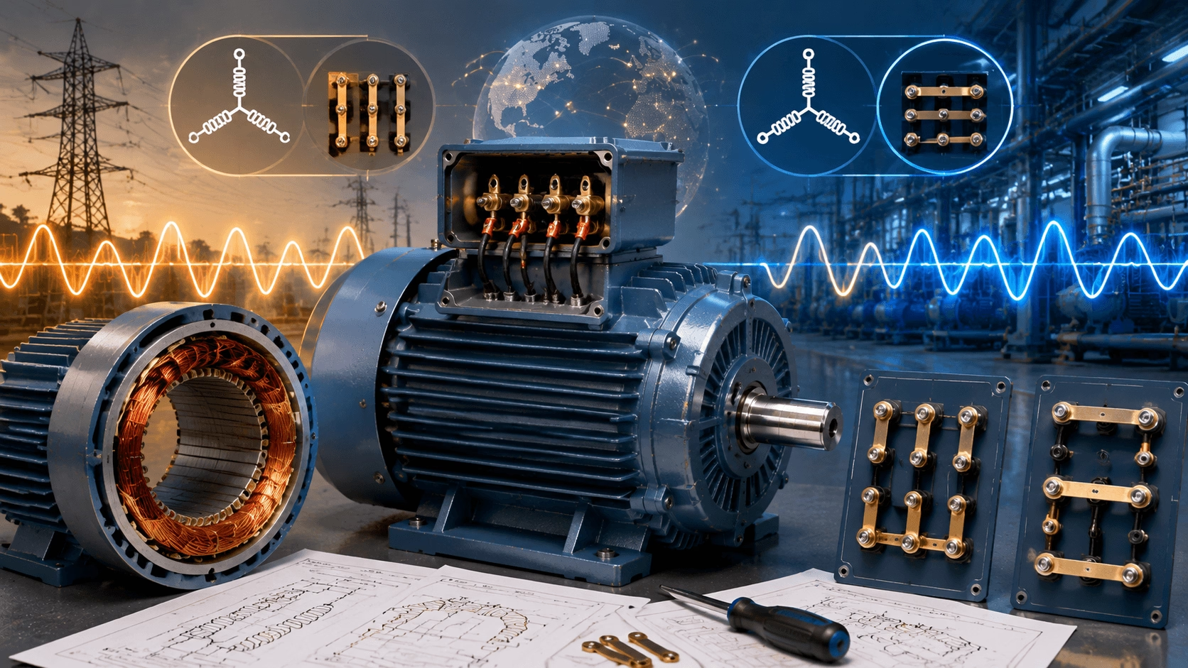
Dual Voltage Motors Explained: The Engineering Behind 230/460V Operation
2026 Industrial Motor Guide: A comprehensive technical analysis of dual-voltage three-phase induction motors. Understand the series/parallel winding principles, terminal box configurations (9-lead/12-lead), efficiency implications, and global application benefits for OEMs, distributors, and facility managers. Compiled with TITECHO engineering expertise.
Introduction: One Motor, Two Voltages?
When inspecting the nameplate of a modern industrial electric motor, you will frequently encounter two voltage ratings listed side-by-side, such as:
- 230/460 V
- 220/380 V
- 240/480 V
- 230/400 V
- 380/660 V
Accompanying these ratings is often a small diagram showing jumper or link positions labeled “Low” and “High” (or “Δ” and “Y”).
At first glance, this seems counterintuitive. How can the same physical machine deliver its full rated power, torque, speed, efficiency, and service life when connected to power supplies that differ by a factor of two?
The answer lies in a deliberate design strategy: the motor is engineered so that each individual turn of copper wire experiences roughly the same voltage stress and current density, regardless of which voltage is applied. This guide provides a thorough, step-by-step explanation of how this is achieved, the trade-offs involved, and why this feature is invaluable in global industrial applications.
1. The Fundamental Design Trick: Split Phase Windings
In a conventional single-voltage motor, each of the three phases consists of one continuous winding group. In a dual-voltage motor (typically designed for a 2:1 voltage ratio), the stator winding for each phase is intentionally constructed as two identical half-windings (or two equal coil groups per phase).
These two halves can be re-connected in the terminal box using brass links, jumpers, or bars. There are only two practical configurations:
| Mode | Connection Style | Voltage Per Half-Winding | Line Current (for Same Power) | Typical Internal Arrangement |
|---|---|---|---|---|
| High Voltage | Series (End-to-End) | V_{line} / 2 | I_{low} / 2 | Single Star (Y) or Single Delta (Δ) |
| Low Voltage | Parallel | V_{line} (the lower value) | \approx 2 \times I_{high} | Double Star (YY) or Double Delta (ΔΔ) |
Why This Works
Because the two halves are electrically and magnetically symmetrical:
- In High-Voltage Mode: The full supply voltage is divided equally across the two series-connected halves. Each half-winding sees only half the line voltage.
- In Low-Voltage Mode: Each half-winding receives the full (lower) line voltage directly via parallel connection.
Result: The Volts-per-Turn remains essentially identical in both configurations. Consequently:
- The magnetic flux density in the air gap stays constant.
- Torque (proportional to Flux × Current) remains unchanged.
- Slip, synchronous speed, rated output power (kW/HP), and efficiency class are preserved.
2. Simplified Analogy: The Resistor Model
To visualize the electrical behavior, imagine replacing each phase winding with two identical resistors (ignoring inductance for a moment):
- Assumption: Each resistor is rated for 230 V and has a resistance of 10 Ω.
Scenario A: High Voltage (Series Connection)
- Total Resistance: 10\,\Omega + 10\,\Omega = 20\,\Omega
- Applied Voltage: 460 V
- Current: I = 460\,V / 20\,\Omega = 23\,A
- Total Power: P = 460\,V \times 23\,A = 10,580\,W
- Heat per Resistor: Each dissipates 5,290\,W.
Scenario B: Low Voltage (Parallel Connection)
- Total Resistance: (10\,\Omega \times 10\,\Omega) / (10\,\Omega + 10\,\Omega) = 5\,\Omega
- Applied Voltage: 230 V
- Current: I = 230\,V / 5\,\Omega = 46\,A (23 A through each branch)
- Total Power: P = 230\,V \times 46\,A = 10,580\,W
- Heat per Resistor: Each still dissipates 5,290\,W.
Conclusion: The total electrical power converted—and therefore the mechanical output power—is identical. Crucially, the heat generated per unit of copper cross-section is also the same. This thermal balance is exactly what a motor designer aims to achieve.
3. Real Terminal Box Configurations
Dual-voltage motors typically come with either 9 or 12 leads brought out to the terminal box.
9-Lead Motors (Most Common for 230/460 V)
- High Voltage (Series/Wye): Connect T4–T7, T5–T8, T6–T9 together. Connect T1, T2, T3 to the power lines.
- Low Voltage (Parallel/Wye-Wye): Connect T4–T5–T6 together. Connect T1–T7, T2–T8, T3–T9 to the power lines.
12-Lead Motors (Maximum Flexibility)
12-lead motors allow for even more configurations, including:
- Wye-Delta Starting (reduces inrush current).
- Part-Winding Starting.
- Dual Voltage (Series/Parallel) in both Wye and Delta arrangements.
⚠️ Critical Warning: Always follow the nameplate diagram exactly. Incorrect jumper placement is one of the top causes of immediate field failures in dual-voltage motors.
4. Important Nuances & Real-World Considerations
Efficiency Differences
- Premium IE3/IE4 Motors: Efficiency variation between high and low voltage modes is typically minimal (0.3–1.2 percentage points).
- Standard/Lower-Cost Motors: Variation can reach 2–4 points, often due to looser winding tolerances or reduced copper fill factors.
Cable & System Savings (High-Voltage Advantage)
Operating in High-Voltage Mode halves the line current. This allows:
- Reduction of feeder cable cross-section by 1–2 sizes.
- Lower material costs for wiring.
- Reduced I^2R losses in the supply wiring.
- Less voltage drop over long distances.
Thermal Behavior
High-voltage mode usually runs slightly cooler at the terminals and bearings due to lower current magnitude. This can be significant in hot, dusty, or poorly ventilated installations where heat dissipation is critical.
Dangerous Misconnection Scenarios
- Low-Voltage Config + High-Voltage Supply: Severe overvoltage. Insulation failure occurs in seconds to minutes.
- High-Voltage Config + Low-Voltage Supply: Severe undervoltage. The motor draws excessive current to try to maintain torque, leading to rapid overheating and potential burnout.
Utility Tolerances
Nameplates often read “230/460 V 60 Hz,” but the motor is designed to tolerate actual utility variations (e.g., 208–240 V / 416–480 V). Always check the fine print for specific tolerance ranges.
5. Why Manufacturers Build Dual-Voltage Motors
From a commercial and operational perspective, this feature delivers outsized value:
- Global Standardization: Equipment builders can ship one motor model to North America (460 V), Europe (400 V), and Asia (380 V), configuring it on-site.
- Inventory Reduction: Distributors and stockists dramatically reduce SKU counts, lowering inventory carrying costs and obsolescence risk.
- User Flexibility: End users gain agility during plant voltage upgrades, generator backup scenarios, or temporary power changes.
- Rental & Mobile Applications: Fleets can adapt quickly between jobsites with different grid voltages without swapping motors.
Quick Field Checklist for Dual-Voltage Motors
✅ Confirm Supply Voltage: Measure the actual line-to-line voltage and ensure it matches one of the nameplate ratings.
✅ Follow the Diagram: Use the exact jumper configuration shown on the nameplate.
✅ Qualified Personnel: Only licensed electricians should perform reconnections. Wrong connections are dangerous and expensive.
✅ Verify Rotation: After reconnection, bump the motor to check rotation direction. Swap any two phases if reversed.
✅ Insulation Test: Megger the windings before first power-up after reconfiguration to ensure no ground faults.
✅ Monitor Temperature: Check initial running temperature during the break-in period to ensure proper cooling.
Conclusion
When handled correctly, dual-voltage capability turns what used to be a major constraint (voltage mismatch) into a non-issue. It is one of the most practical engineering conveniences in modern industrial electric motors, preserving full nameplate performance at either voltage without derating, rewinding, or external transformers.
If you’re evaluating motors for a new project, export application, or multi-voltage facility, understanding this reconnection principle helps you specify and maintain the right equipment with confidence.
Get a Free Custom Quote for Copper Motors
Choose TITECHO's 99.99% pure copper winding motors for lower operational costs, longer equipment life, and compliance with 2026 energy regulations. Our team responds within 24 hours!
- ✉️ Email: [email protected]
TITECHO – TECHO ELECTRICAL & MECHANICAL (TAIZHOU) CO., LTD
Taizhou City, Zhejiang, China | www.cntecho.com | ISO 9001 Certified | Leading Manufacturer of IE3/IE4 Ultra-High Efficiency Motors