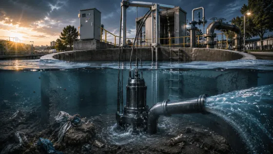
1. Introduction: Why Submersible Pumps Dominate Wastewater Engineering
The submersible sewage pump is arguably the most important innovation in wastewater infrastructure since the invention of the centrifugal pump itself. By integrating the motor and hydraulic end into a single hermetically sealed unit that operates fully submerged, submersible pumps eliminate the three greatest failure modes of conventional pump installations: suction lift limitations, priming requirements, and cavitation risk.
Unlike surface-mounted pumps that pull liquid upward through suction piping, a submersible pump pushes fluid from below. The impeller inlet is inherently flooded, creating positive inlet pressure that makes cavitation virtually impossible under normal conditions. The surrounding wastewater itself becomes the cooling medium, enabling compact, high-power-density motor designs that would overheat in seconds if exposed to air.
This guide covers the complete engineering lifecycle of submersible sewage pumps—from motor thermodynamics and seal technology to wet well hydraulics and system integration.
2. Submersible vs. Dry-Pit: The Installation Engineering Decision
Before selecting a pump, you must choose the installation architecture. This decision locks in your civil engineering costs, maintenance strategy, and operational envelope for decades.
Table 1: Wet-Pit vs. Dry-Pit Submersible Installation Comparison
| Engineering Parameter | Wet-Pit (Fully Submerged) | Dry-Pit (Cooling Jacket or Air-Cooled) |
|---|---|---|
| Pump Location | Directly submerged in wet well liquid | Installed in dry chamber adjacent to wet well |
| Motor Cooling | Passive: surrounding liquid absorbs heat | Active: closed-loop cooling jacket or forced air |
| IP Rating Required | IP68 (continuous submersion beyond 1 m) | IP55–IP65 (splash protection; jacketed IP68) |
| Suction Config. | Flooded suction (positive inlet pressure) | Requires suction piping from wet well to pump |
| Priming | Inherently primed (always submerged) | Requires priming system or self-priming design |
| NPSH Available | High (submergence + atm. pressure − friction) | Lower (must account for suction lift & friction) |
| Cavitation Risk | Minimal to none | Moderate; must verify NPSH_a > NPSH_r + margin |
| Footprint | Minimal surface area (only access hatch) | Requires dedicated pump room (400–800 sq ft) |
| Noise Level | Very low (liquid dampens motor acoustics) | Moderate to high (exposed motor and pump) |
| Maintenance Access | Requires guide rail + overhead crane/hoist | Direct walk-in access; in-situ repair possible |
| Capital Cost | 30–40% lower initial investment | 30–40% higher initial investment |
| 20-Year TCO | Higher for stations > 500 GPM (removal costs) | Lower for large stations (in-situ maintenance) |
| Best Application | Municipal lift stations, basements, sumps | Large municipal stations, high-temp effluent |
Critical Rule for Wet-Pit: Passive-cooled submersible motors must remain fully submerged during continuous duty (S1) operation. If the liquid level drops below the motor housing, the motor overheats within minutes. Minimum submergence must be maintained by level control systems with redundant float switches.
3. Motor Thermodynamics: The Science of Submerged Cooling
The defining engineering challenge of any submersible pump is thermal management. The motor generates heat from electrical losses (I²R in windings, core losses in laminations, friction in bearings). In a wet-pit installation, this heat must transfer through the motor housing into the surrounding wastewater. If the heat transfer rate is insufficient, winding temperature rises until insulation fails.
Formula 1: Motor Heat Transfer & Temperature Rise
The steady-state motor winding temperature in a wet-pit submersible pump is governed by:
T_winding = T_fluid + ΔT_housing + ΔT_insulation
Where:
- T_fluid = Temperature of surrounding wastewater (°C)
- ΔT_housing = Temperature rise across motor housing = P_loss / (h · A_cooling)
- P_loss = Total motor losses (kW) = P_motor · (1 - η_motor)
- h = Convective heat transfer coefficient (W/m²·K) — ~500–800 for free convection in water
- A_cooling = Wetted surface area of motor housing (m²)
- ΔT_insulation = Temperature rise from housing to winding hotspot (°C) — typically 30–50°C
Example Calculation:
A 15 kW submersible motor with 92% efficiency operating in 20°C sewage:
P_loss = 15 · (1 - 0.92) = 1.2 kW
For a motor with A_cooling = 0.8 m² and h = 600 W/m²·K:
ΔT_housing = 1200 / (600 · 0.8) = 2.5°C
With ΔT_insulation = 40°C:
T_winding = 20 + 2.5 + 40 = 62.5°C
(This is well below the Class F limit of 155°C, confirming safe continuous operation.)
Formula 2: Minimum Submergence for Thermal Stability
To ensure the motor housing remains fully wetted and cooling is effective:
S_min = P_loss / (h_eff · π · D_motor · ΔT_max) + S_safety
Where:
- h_eff = Effective heat transfer coefficient (W/m²·K)
- D_motor = Motor outer diameter (m)
- ΔT_max = Maximum allowable temperature rise of housing above fluid (°C)
- S_safety = Safety margin (typically 0.15–0.30 m)
Practical Rule: For standard submersible sewage pumps, maintain minimum 0.3–0.5 m of liquid above the motor top during all operating conditions. For high-power motors (> 30 kW) or hot fluids (> 35°C), increase to 0.8–1.0 m.
4. Motor Insulation Classes & Protection Systems
Submersible motors operate in the harshest electrical environment imaginable: submerged in conductive, corrosive liquid with limited heat dissipation paths. Insulation class selection determines both safety margin and service life.
Table 2: Motor Insulation Class Specifications
| Insulation Class | Max Winding Temp | Temp Rise @ 40°C Ambient | Typical Application | Expected Life |
|---|---|---|---|---|
| Class B | 130°C | 80°C | Light-duty drainage, intermittent | 10,000–15,000 hrs |
| Class F | 155°C | 105°C | Standard sewage duty, continuous S1 | 20,000–30,000 hrs |
| Class H | 180°C | 125°C | Heavy-duty industrial, high-temp | 30,000–50,000 hrs |
Temperature Rise De-rating for Hot Fluids:
If the pumped fluid exceeds 40°C, the allowable temperature rise must be reduced:
ΔT_allowable = T_insulation,max - T_fluid - 10°C (safety margin)
For Class F insulation with 50°C sewage:
ΔT_allowable = 155 - 50 - 10 = 95°C
(This is within the 105°C standard rating, but with reduced safety margin. For fluids > 55°C, specify Class H insulation or install a cooling jacket.)
Motor Protection Sensors (Standard on Quality Pumps)
| Sensor Type | Function | Trigger Point | Response |
|---|---|---|---|
| MTS (Motor Thermal) | Bimetal strip in each stator phase | 140°C (Class F) | Control panel opens circuit; auto-reset |
| BTS (Bearing Temp) | RTD in lower bearing housing | 100°C (alarm); 120°C (trip) | Indicator alarm; panel shutdown at trip |
| MS (Moisture) | Electrode in seal oil chamber | Water ingress detected | Immediate shutdown; prevents motor flooding |
| Leakage Detector | Float switch in motor housing | Oil/water accumulation | Alarm + pump shutdown |
These sensors are mandatory on pumps ≥ 11 kW (15 HP) and strongly recommended on all sewage duty pumps.
5. Mechanical Seal Technology: The Critical Barrier
The mechanical seal is the most vulnerable component in any submersible pump. It must prevent wastewater from entering the motor while the shaft rotates at 1450–2900 RPM. Submersible pumps universally use double mechanical seals in an oil-filled chamber.
Table 3: Mechanical Seal Configuration
| Seal Position | Primary Seal | Secondary Seal | Oil Chamber Function |
|---|---|---|---|
| Lower Seal (Pump Side) | SiC/SiC or WC/SiC | SiC/SiC | Lubricates/cools faces; detects failure via moisture sensor |
| Upper Seal (Motor Side) | Carbon/Ceramic or SiC/SiC | SiC/SiC | Final barrier before motor; operates in clean oil |
Seal Face Material Selection:
| Wastewater Type | Primary Seal | Secondary Seal | Elastomer | Expected Life |
|---|---|---|---|---|
| Standard municipal | SiC/SiC | SiC/SiC | Viton (FKM) | 15,000–25,000 hrs |
| Abrasive (sand, grit) | Tungsten Carbide/SiC | SiC/SiC | Viton | 8,000–15,000 hrs |
| High temp (> 50°C) | SiC/SiC | SiC/SiC | FFKM (Kalrez) | 12,000–20,000 hrs |
| Chemical (pH < 5) | SiC/SiC | SiC/SiC | EPDM or FFKM | 10,000–18,000 hrs |
| Seawater / marine | SiC/SiC | SiC/SiC | EPDM | 15,000–25,000 hrs |
Critical Installation Note: The oil chamber must be filled with food-grade white oil (ISO VG 32 or 46) during assembly. Never operate without oil—dry seal faces destroy themselves within seconds.
6. Performance Analysis: The Complete Operating Envelope
Chart 1: Submersible Pump Motor Temperature & Performance Map
Left Panel — Motor Temperature vs. Submergence Depth:
- Wet-Pit Passive Cooling (Blue): At full submergence (> 3.5 m), winding stabilizes at ~25°C above fluid temp. For 20°C sewage, this means ~45°C winding temp—comfortable margin under Class F (155°C) limits.
- Dry-Pit Active Cooling (Green): With a cooling jacket, temps are slightly higher due to jacket wall resistance, but still safe across all depths.
- Dry-Run Condition (Red): Without liquid cooling, motor temp climbs catastrophically. At 1 m "submergence" (effectively exposed), temp exceeds 100°C within minutes. This is the motor burnout zone.
- The purple vertical line at 3.5 m marks the minimum submergence for S1 continuous duty.
Right Panel — Performance Map with Efficiency Contours:
- Green/Yellow zones (η > 66%): High-efficiency region. BEP at Q = 80 m³/h, H = 25 m achieves 78% efficiency.
- Orange/Red zones (η < 54%): Operating far from BEP wastes energy and accelerates wear.
- White curves: Pump curves for 2-pole (2900 RPM), 4-pole (1450 RPM), and 6-pole (960 RPM) motors.
- Colored system curves: Show where three typical systems intersect the pump curves.
Key Insight: The 4-pole (1450 RPM) configuration offers the best compromise between head capability, efficiency, and solids handling for most sewage applications. 2-pole pumps achieve higher heads but suffer from increased wear. 6-pole pumps are ideal for large solids and low-speed abrasion resistance.
7. Hydraulic Formulas for Submersible Pump Selection
Formula 3: Total Dynamic Head (TDH)
Submersible pumps eliminate suction lift, simplifying TDH calculation:
TDH = H_static + H_friction + H_discharge
Where:
- H_static = Vertical distance from lowest operating liquid level to discharge free surface (m)
- H_friction = f · (L/D) · (v² / 2g) + ΣK · (v² / 2g) — Major + minor losses in discharge piping
- H_discharge = P_discharge / (ρ · g) — Pressure head at point of discharge
Sewage-Specific Friction Factors:
| Pipe Condition | Friction Factor Multiplier |
|---|---|
| New pipe, clean sewage | 1.10–1.20 × clean water |
| Pipe with moderate biofilm | 1.25–1.40 × clean water |
| Pipe with heavy scale/deposits | 1.50–2.00 × clean water |
Always design for the worst-case condition over the pump's service life.
Formula 4: NPSH Available for Submersible Pumps
The submersible pump's greatest advantage is its inherently high NPSH_a:
NPSH_a = (P_atm / (ρ · g)) + H_sub - (P_vapor / (ρ · g)) - H_f,suction - H_vol
For submersible pumps:
- H_sub = Submergence depth above impeller eye (m) — always positive
- H_f,suction ≈ 0 (no suction piping in wet-pit installation)
- H_vol = Volatile gas head (0.5–1.5 m for septic sewage)
Simplified for standard conditions:
NPSH_a ≈ 10.3 - H_vol + H_sub
At 3.5 m submergence with H_vol = 1.0 m:
NPSH_a = 10.3 - 1.0 + 3.5 = 12.8 m
(This is typically 3–5× higher than the pump's NPSH_r, providing an enormous cavitation safety margin.)
Formula 5: Required Motor Power
P_motor = (Q · H · ρ · g) / (3,600,000 · η_p · η_m) · SF
Where:
- Q = Flow rate (m³/h)
- H = Total dynamic head (m)
- ρ = Fluid density (1020–1050 kg/m³ for sewage)
- η_p = Pump efficiency (0.50–0.84)
- η_m = Motor efficiency (0.88–0.95)
- SF = Service factor (1.15 for standard; 1.25 for high-solids/abrasive duty)
Example: Submersible pump for 100 m³/h at 30 m head, ρ = 1025 kg/m³, η_p = 0.75, η_m = 0.92:
P_motor = (100 · 30 · 1025 · 9.81) / (3,600,000 · 0.75 · 0.92) · 1.15 = 17.4 kW
Select next standard size: 18.5 kW (25 HP) or 22 kW (30 HP) for margin.
8. Wet Well Design for Submersible Pumps
Table 4: Wet Well Design Parameters
| Parameter | Residential | Commercial | Municipal | Engineering Basis |
|---|---|---|---|---|
| Minimum diameter | 0.9 m (36") | 1.2 m (48") | 1.5 m (60") | Pump removal clearance |
| Minimum depth | 1.5 m | 2.0 m | 2.5 m | Submergence + inlet clearance |
| Floor slope | 1:10 to pump | 1:10 to pump | 1:8 to pump | Solids transport to intake |
| Inlet pipe elevation | Above max liquid level | Above max liquid level | Above max liquid level | Prevent backflow & short-circuiting |
| Pump spacing | N/A | 1.5 × impeller dia. | 2.0 × impeller dia. | Hydraulic interference prevention |
| Min. cycle time | 6 minutes | 8 minutes | 10 minutes | Motor thermal protection |
| Ventilation | 6 ACH minimum | 6 ACH minimum | 12 ACH + H₂S detection | OSHA/confined space safety |
Formula 6: Wet Well Working Volume for Cycle Time Control
Excessive cycling destroys motor windings. The minimum working volume is:
V_working = (Q_pump · t_min) / 4
Where:
- Q_pump = Pump discharge rate (m³/min)
- t_min = Minimum allowable cycle time (minutes)
- Factor of 4 accounts for inflow continuing during pump operation
Example: 30 kW pump delivering 2.0 m³/min (120 m³/h), with 10-minute minimum cycle:
V_working = (2.0 · 10) / 4 = 5.0 m³
For a 1.5 m × 1.5 m wet well, the level differential is:
ΔH = 5.0 / (1.5 · 1.5) = 2.22 m
Set pump-on at 1.5 m above floor, pump-off at 3.72 m above floor.
Formula 7: Inlet Velocity & Approach Conditions
To prevent vortexing and air entrainment:
v_approach = Q / A_wetwell < 0.3 m/s
And the minimum distance from inlet pipe to pump intake:
L_min = 5 · D_inlet
Where D_inlet is the inlet pipe diameter. This prevents direct jet impingement on the pump and ensures uniform flow distribution.
9. Guide Rail System & Maintenance Engineering
The guide rail system (GRS) is what makes wet-pit submersible pumps maintainable. Without it, pump removal requires draining the wet well—an expensive and hazardous operation.
Table 5: Guide Rail System Components & Specifications
| Component | Material | Specification | Function |
|---|---|---|---|
| Guide Rails | Hot-dip galv. steel or 316 SS | 50×50 mm angle or 60 mm round, min 5mm wall | Vertical tracks for pump guidance |
| Upper Bracket | Cast iron or steel | Bolted to wet well top slab | Supports rail tops; carries chain hoist load |
| Discharge Elbow | Cast iron ASTM A48 CL30 | Flanged connection, DN 50–400 | Stationary discharge connection at wall |
| Duckfoot Bend | Cast iron with bronze wear ring | Matches pump discharge flange | Self-aligning connection to discharge elbow |
| Lifting Chain | 316 SS, grade 80 | SWL = 3× pump weight | Hoist attachment for pump removal |
| Chain Hoist | Electric or manual | Capacity ≥ 1.5× pump weight | Raises/lowers pump along rails |
Installation Sequence:
- Lower discharge elbow and secure to wet well wall.
- Install guide rails from top bracket to floor brackets.
- Lower pump with duckfoot bend engaged to rails.
- Pump weight seats duckfoot into elbow, creating seal.
- Connect power cable through sealed entry.
Removal for Service:
- Disconnect power at panel.
- Attach lifting chain to pump lifting eye.
- Hoist pump upward—duckfoot disengages from elbow.
- Pump slides up rails to surface for maintenance.
- Reverse for reinstallation (typically < 30 minutes).
10. Material Selection for Submersible Sewage Pumps
Table 6: Complete Material Specification Matrix
| Component | Standard Municipal | Abrasive/Industrial | Marine/Seawater | Chemical Aggressive |
|---|---|---|---|---|
| Pump Casing | Cast Iron FC200 / ASTM A48 | Ductile Iron FCD500 | Duplex SS 2205 / CD4MCu | Super Duplex 2507 |
| Impeller | Cast Iron FC200 or CF-8M | High-Chrome Iron (28% Cr) | Super Duplex 2507 | Hastelloy C |
| Motor Housing | Cast Iron FC200 | Cast Iron + ceramic coating | 316 SS | 316 SS |
| Shaft | 420 SS / ASTM 410 | 17-4 PH SS | 316 SS | Alloy 20 |
| Mech. Seal Faces | SiC/SiC | WC/SiC | SiC/SiC | SiC/SiC |
| Seal Elastomers | Viton (FKM) | Viton (FKM) | EPDM | FFKM (Kalrez) |
| Fasteners | 304 SS | 316 SS | 316 SS | Hastelloy C |
| Cable | VCT or SOOW rubber | PNCT heavy-duty | Marine-grade SOOW | Chemical-resistant CPE |
| Coating (external) | Epoxy paint 250 μm | Ceramic-filled epoxy 500 μm | Thermal spray aluminum | Rubber lining 3 mm |
H₂S Corrosion Warning: In septic conditions (anaerobic, low dissolved oxygen), hydrogen sulfide gas forms and converts to sulfuric acid on moist surfaces. This can penetrate cast iron at rates exceeding 1 mm/year. For H₂S-prone applications, specify duplex stainless steel casings or apply cathodic protection systems.
11. Electrical Engineering & Control Systems
Table 7: Electrical Specifications by Power Rating
| Parameter | 0.37–2.2 kW | 3.0–7.5 kW | 11–30 kW | 37–75 kW |
|---|---|---|---|---|
| Voltage | 1-ph 220V or 3-ph 380V | 3-phase 380V | 3-phase 380–415V | 3-phase 380–690V |
| Starting Method | DOL or Star-Delta | Star-Delta or Soft Starter | Soft Starter or VFD | VFD (mandatory) |
| Protection | Thermal overload relay | Thermal + phase loss | MTS + BTS + MS + VFD | Full instrumentation + SCADA |
| Cable Entry | Single cable gland | Single cable gland | Double compression gland | Double compression + support |
| Control Panel | Basic float switch | Float + ultrasonic backup | PLC with alternation | PLC + HMI + remote monitoring |
| IP Rating (panel) | IP55 | IP55 | IP65 | IP65 |
Three-Phase Rotation Verification:
Submersible pumps rotate counter-clockwise when viewed from the bottom (impeller side). Reverse rotation reduces flow by 50–70%, causes severe vibration, and overloads thrust bearings.
Always verify rotation before submersion:
- Momentarily energize motor (bump start).
- Observe shaft rotation direction.
- If reversed, swap any two phases at the control panel.
12. Energy Efficiency & Lifecycle Cost Analysis
Table 8: 15-Year Lifecycle Cost Comparison — Submersible vs. Dry-Pit
| Cost Component | Wet-Pit Submersible (2× 15 kW) | Dry-Pit (2× 15 kW) |
|---|---|---|
| Initial Equipment | $28,000 | $42,000 |
| Civil Works | $18,000 (compact wet well) | $55,000 (pump room + dry well) |
| Installation | $8,000 | $15,000 |
| Energy (15 yr, $0.12/kWh) | $118,000 | $112,000 |
| Maintenance & Parts | $32,000 (removal/replacement costs) | $18,000 (in-situ access) |
| Downtime / Emergency | $22,000 | $8,000 |
| Residual Value | -$4,000 | -$6,000 |
| TOTAL LCC | $222,000 | $244,000 |
Conclusion: For small-to-medium stations (< 500 GPM), wet-pit submersible pumps offer lower total lifecycle cost despite higher maintenance overhead. For large stations (> 750 GPM) with continuous duty, dry-pit installations become economically favorable due to in-situ maintenance efficiency.
13. Troubleshooting Guide for Submersible Sewage Pumps
| Symptom | Diagnostic Procedure | Root Cause | Corrective Action |
|---|---|---|---|
| No flow, motor running | Check amp draw; inspect discharge | Impeller clogged; broken shaft; reverse rotation | Remove pump; clear impeller; verify phase sequence |
| Low flow, normal amps | Compare to baseline curve | Worn impeller; partial clog; discharge valve closed | Inspect impeller clearance; check valve position |
| High amps, low flow | Check for mechanical binding | Bearing seizure; impeller rubbing casing; solids jam | Remove pump; inspect bearings; check clearances |
| Seal leakage (oil chamber) | Check moisture sensor; inspect oil | Lower seal failure; dry-running event | Replace both seals; refill oil chamber |
| Motor overheating (MTS) | Check submergence; verify cooling | Insufficient liquid level; blocked cooling passages | Adjust level controls; clean motor jacket |
| Excessive vibration | Vibration analysis (ISO 10816) | Impeller imbalance; bearing wear; cavitation | Balance impeller; replace bearings; verify NPSH |
| Frequent cycling | Review level settings; check inflow | Wet well volume too small; float switch malfunction | Recalculate working volume; replace floats |
| H₂S odor in wet well | Test atmosphere; check ventilation | Anaerobic conditions; insufficient turnover | Increase ventilation; reduce detention time |
14. Conclusion: Engineering Reliability Beneath the Surface
The submersible sewage pump represents a triumph of integration engineering. By sealing the motor within the fluid it pumps, designers eliminated suction limitations, priming failures, and cavitation risk in a single design decision. But this integration comes with its own engineering demands: thermal management through submergence, hermetic sealing against corrosive fluids, and maintenance strategies that work around submerged installation.
Success with submersible pumps requires discipline in three areas:
- Hydraulic design — Proper TDH calculation, system curve matching, and BEP operation.
- Thermal design — Maintaining minimum submergence for motor cooling, selecting appropriate insulation class.
- Mechanical design — Specifying correct seal materials, guide rail systems for maintainability, and corrosion-resistant construction.
The formulas, performance maps, and specification tables in this guide provide the technical foundation for confident submersible pump engineering in any wastewater application—from a single residential basement pump to a municipal lift station processing 500 m³/h.
Need Application-Specific Submersible Pump Specification?
Our engineering team provides complimentary hydraulic analysis, thermal verification, and wet well design review. Submit your flow requirements, site conditions, and wastewater characteristics for a detailed technical proposal including pump curves, installation drawings, and control panel specifications.
Technical references: Wilo Wet-Pit vs. Dry-Pit Installation Guide, HCP Pump AF Series Specifications, BB Pump ASW Series Catalog, Evergush EAF Heavy Duty Pumps, Grampus BL Series Oil-Type Motors, Solidpump TBZE Dewatering Pumps, DAB Pump Selection Quick Guide, ScienceDirect Cavitation & Erosion Research (2024), CNT Echo Submersible Pump Technical Guide, Pump Professionals Submersible vs. Dry-Pit Analysis.