1. Introduction: Why Rainwater Pump Engineering Matters
Rainwater harvesting and stormwater management have evolved from simple gravity-fed systems into sophisticated engineered networks. Whether you are designing a residential harvesting system, a commercial stormwater retention facility, or an industrial dewatering station, the rainwater pump is the critical heart of the system. An undersized pump leads to flooding and property damage; an oversized pump wastes energy, induces cavitation, and shortens equipment life.
This guide provides the hydraulic fundamentals, selection formulas, and comparative data you need to specify the right pump with engineering confidence.
2. Rainwater Pump Types: A Technical Comparison
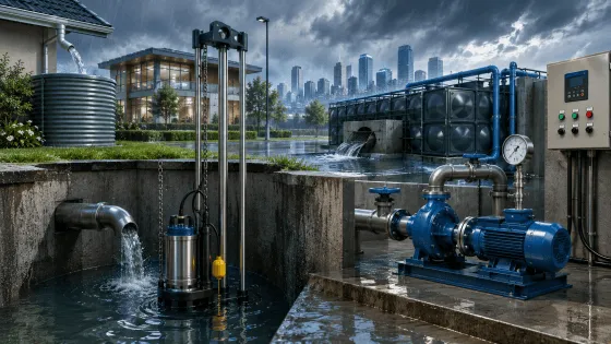
Rainwater pumps fall into two primary categories based on installation geometry: Submersible (Wet-Pit) and Dry-Pit configurations. The choice between them determines your civil engineering costs, maintenance accessibility, and long-term operational efficiency.
Table 1: Wet-Pit vs. Dry-Pit Installation Comparison
| Technical Aspect | Wet-Pit (Submersible) Installation | Dry-Pit Installation |
|---|---|---|
| Pump Location | Submerged directly in the rainwater sump/wet well | Installed in a dry, accessible pump room adjacent to the liquid source |
| Cooling Method | Passive cooling via surrounding rainwater (requires continuous submersion for S1 duty) | Active cooling via closed-loop jacket or air circulation |
| Footprint | Compact (150–300 sq ft for standard stations) | Larger (400–800 sq ft required for pump room and piping) |
| Noise Level | Very low (liquid dampens motor acoustics) | Higher (exposed motor and pump components) |
| Maintenance Access | Requires lifting equipment (guide rails or chains) for removal | Direct walk-in access; no confined space entry required |
| Priming Requirement | None (pump is inherently submerged and primed) | Requires priming systems or self-priming pump design |
| Suction Piping | Eliminated (direct intake from sump) | Required; suction losses must be calculated in TDH |
| Initial Cost | Lower pump cost; higher civil cost for deep wet well | Higher pump cost (cooling jacket, robust frame); lower civil cost |
| Best Application | Stormwater lift stations, underground harvesting tanks, sewage mixed rainwater | Clean rainwater transfer, above-ground tank systems, hygienic environments |
Sources: Wilo Technical Training Documentation; Pump Professionals Industry Analysis
3. Core Hydraulic Formulas for Pump Selection
Before selecting a pump model, you must calculate the Total Dynamic Head (TDH) and verify power requirements. These are not optional estimates—they are the foundation of proper pump sizing.
Formula 1: Total Dynamic Head (TDH)
The TDH represents the total equivalent height the pump must overcome, accounting for elevation, pressure, and friction.
TDH = H_static + H_pressure + H_friction
Where:
- H_static = Vertical distance from pump centerline to discharge free surface (m)
- H_pressure = (P_d - P_s) / (ρ · g) — Pressure head differential converted to meters of water column
- H_friction = Major losses (Darcy-Weisbach) + Minor losses (valves/fittings)
Darcy-Weisbach Equation for Major Friction Loss:
h_f = f · (L / D) · (v² / 2g)
Where:
- f = Darcy friction factor (dimensionless, from Moody chart)
- L = Total pipe length (m)
- D = Internal pipe diameter (m)
- v = Flow velocity (m/s)
- g = Gravitational acceleration (9.81 m/s²)
Minor Losses (Fittings & Valves):
h_m = Σ K · (v² / 2g)
Where K is the loss coefficient for each fitting (e.g., 90° elbow K ≈ 0.9; fully open gate valve K ≈ 0.2).
Formula 2: Brake Horsepower (BHP) & Motor Sizing
Once TDH is established, calculate the power required at the pump shaft:
BHP = (Q · H · ρ) / (3,960 · η_p)
(Imperial units: Q in GPM, H in ft, ρ in lb/gal)
Or in metric units:
P_shaft (kW) = (Q(m³/s) · H(m) · ρ(kg/m³) · g) / (1,000 · η_p)
Where η_p = pump efficiency (decimal, typically 0.65–0.85 for centrifugal pumps).
Motor Input Power:
P_motor = P_shaft / η_motor
Always apply a 1.15–1.25 service factor for continuous rainwater duty cycles and potential debris loading.
Sources: Grundfos Pump Hydraulics Basics; Pennsylvania DEP Pump Training Module
4. Understanding Pump Performance Curves
A pump performance curve is the "resume" of a pump's hydraulic capability. It plots the relationship between Flow Rate (Q) and Total Head (H) for a given impeller diameter and rotational speed.
Chart 1: Rainwater Pump Performance Curve (RWP-150 Series)
How to Read This Chart:
- Head-Capacity Curves (Blue/Green/Red): These show how much head the pump generates at different flow rates. As flow increases, head decreases—a fundamental characteristic of centrifugal pumps.
- System Curve (Purple): This represents your piping network's resistance. It starts at the static head and rises parabolically with flow due to friction.
- Operating Point (Blue Square): The intersection of the pump curve and system curve. This is where the pump will actually run. For this example, the operating point is approximately Q = 86.2 m³/h at H = 37.4 m.
- Best Efficiency Point (BEP): The peak of the orange efficiency curve. Operating near the BEP (here at Q = 60 m³/h, H = 28.5 m, η = 78%) ensures maximum energy efficiency and minimum bearing/seal wear.
- NPSHr Curve (Cyan Dotted): The Net Positive Suction Head Required by the pump to avoid cavitation. You must ensure your system's NPSH Available exceeds this value by at least 0.5–1.0 m.
Affinity Laws (For Variable Speed or Impeller Trimming)
If your calculated duty point does not match the standard curve, you can adjust performance using the Affinity Laws:
| Parameter | Speed Change (N₂/N₁) | Impeller Diameter Change (D₂/D₁) |
|---|---|---|
| Flow Rate Q₂/Q₁ | N₂/N₁ | D₂/D₁ |
| Head H₂/H₁ | (N₂/N₁)² | (D₂/D₁)² |
| Power P₂/P₁ | (N₂/N₁)³ | (D₂/D₁)³ |
Sources: DHK Pump Engineering Guide; Sugar Process Tech Pump Formulas
5. Practical Selection Guide: Matching Pump to Application
Table 2: Rainwater Pump Specification Matrix by Application
| Application | Typical Flow (Q) | Typical Head (H) | Recommended Pump Type | Key Features | Power Range |
|---|---|---|---|---|---|
| Residential Garden/Hose | 30–60 L/min (1.8–3.6 m³/h) | 10–20 m | Small Submersible or Jet Pump | Auto pressure switch, run-dry protection | 0.37–0.75 kW (0.5–1 HP) |
| Household Plumbing | 20–45 L/min (1.2–2.7 m³/h) | 15–25 m | Multi-stage Jet or Booster Pump | Rains-to-mains auto-switch, potable approval | 0.55–1.1 kW (0.75–1.5 HP) |
| Small Commercial Building | 5–15 m³/h | 20–35 m | Submersible Drainage Pump | Float switch, solids handling up to 35 mm | 1.5–3.0 kW (2–4 HP) |
| Stormwater Lift Station | 15–60 m³/h | 15–40 m | Wet-Pit Submersible (Vortex/Channel) | Guide rail installation, IP68 motor, 316 SS hardware | 5.5–15 kW (7.5–20 HP) |
| Industrial Dewatering | 50–300+ m³/h | 10–30 m | Dry-Pit or Portable Submersible | High abrasion resistance, 24-hour continuous duty | 11–75 kW (15–100 HP) |
Sources: APR Tanks Pump Selection Guide; ESCO Water Pump Guide
6. Critical Installation & Safety Considerations
Run-Dry Protection
Rainwater tanks can empty during dry seasons. Operating a pump without liquid causes immediate seal failure and motor burnout. Specify pumps with:
- Thermal overload sensors embedded in the motor windings
- Float switches or electrode-based level controllers with low-water cutoff
- Dry-run mechanical seals (e.g., silicon carbide vs. carbon) for intermittent accidental exposure
Electrical Safety in Wet Environments
All submersible rainwater pumps must carry IP68 enclosure ratings (continuous submersion beyond 1 meter). Additionally:
- Use H07RN-F heavy-duty rubber cables with watertight cable entry glands
- Install GFCI/RCD protection (30 mA sensitivity) on all single-phase installations
- For three-phase motors, verify phase sequence to prevent reverse rotation, which reduces flow by 50%+ and overloads bearings
Material Selection for Rainwater
While rainwater is generally clean, roof runoff can contain debris, pollen, and acidic compounds. Material compatibility ensures longevity:
| Component | Standard Duty | Heavy Duty / Coastal |
|---|---|---|
| Pump Casing | Cast Iron (ASTM A48 Class 30) | Duplex Stainless Steel 2205 |
| Impeller | Cast Iron or Bronze | 316 Stainless Steel or CD4MCu |
| Shaft | 420 Stainless Steel | 316 Stainless Steel |
| Mechanical Seal | Carbon/Ceramic/Buna-N | Silicon Carbide/Silicon Carbide/Viton |
| Fasteners | Zinc-plated Steel | 316 Stainless Steel |
7. Energy Efficiency & Lifecycle Cost Analysis
Pump selection should not be based on purchase price alone. The Lifecycle Cost (LCC) methodology reveals the true economic impact:
LCC = C_initial + C_energy + C_maintenance + C_downtime - C_residual
Where energy cost dominates over a 10–15 year lifespan:
C_energy = (P_motor · t_annual · c_electricity) / (η_motor · η_pump · η_VFD)
Example Calculation:
A 7.5 kW pump running 2,000 hours/year at $0.12/kWh:
| Scenario | Pump η | Motor η | Annual Energy Cost | 10-Year Cost |
|---|---|---|---|---|
| Poor Selection (Oversized) | 55% | 88% | $3,719 | $37,190 |
| Standard Selection | 72% | 91% | $2,838 | $28,380 |
| Optimized Selection (VFD + BEP) | 78% | 94% | $2,553 | $25,530 |
Savings from optimized selection: $11,660 over 10 years—often exceeding the initial pump cost.
8. Maintenance Protocol & Troubleshooting
Table 3: Preventive Maintenance Schedule
| Interval | Action Item | Indicator of Required Action |
|---|---|---|
| Monthly | Visual inspection of sump; check for debris accumulation | Float switch malfunction; reduced flow |
| Quarterly | Check seal leakage (acceptable: <5 drops/min); inspect cable entry | Visible water in motor chamber (if seal leak detector fitted) |
| Semi-Annually | Vibration analysis; check bearing temperature | ISO 10816 vibration velocity > 4.5 mm/s RMS |
| Annually | Pull pump for impeller clearance check; replace mechanical seal | Head drop > 10% from baseline; power increase > 15% |
| 5 Years | Rewind motor insulation test (Megger > 100 MΩ); replace bearings | Insulation resistance < 10 MΩ |
Common Fault Diagnostics
| Symptom | Probable Cause | Engineering Solution |
|---|---|---|
| No flow, motor running | Impeller clogged with debris; broken shaft | Remove pump; inspect impeller; check coupling alignment |
| Low flow, high power | Operating far left of curve (throttled); worn impeller | Trim impeller or adjust VFD speed; replace impeller |
| Excessive vibration | Bearing wear; impeller imbalance; cavitation | Vibration analysis; check NPSH_a vs. NPSH_r; rebalance impeller |
| Seal leakage | Seal face damage; dry-running event | Replace mechanical seal; verify level control system |
| Motor overheating | High ambient; phase imbalance; overload | Check cooling jacket; verify voltage balance within 2% |
9. Conclusion: Engineering Excellence in Rainwater Management
Selecting a rainwater pump is not a catalog exercise—it is a hydraulic engineering decision. By applying the TDH calculation, verifying NPSH margins, analyzing performance curves, and selecting materials for your specific water chemistry, you ensure reliable, efficient, and long-lasting operation.
The formulas, tables, and performance chart in this guide provide the technical foundation for confident specification. Whether you are a consulting engineer, a facility manager, or a contractor, rigorous application of these principles will deliver superior project outcomes.
Need Application-Specific Pump Selection?
Our engineering team provides complimentary hydraulic calculations and pump curve matching for your specific rainwater system. Contact us with your flow requirements, static head, and piping layout for a detailed technical proposal.
Technical references: Grundfos Pump Hydraulics, Wilo Submersible Installation Guidelines, DHK Pump Engineering Handbook, APR Tanks Selection Guide, Pennsylvania DEP Pump Training Module, Sugar Process Tech Pump Formulas.