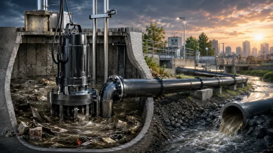
1. Introduction: The Engineering Challenge of Sewage Pumping
Sewage pumping is fundamentally different from clean water applications. Raw sewage contains suspended solids, fibrous materials, grease, and unpredictable debris—from sanitary products to construction waste. A pump designed for clean water will clog within hours in sewage service. Conversely, an over-engineered grinder pump in a simple residential application wastes capital and energy.
This guide provides the hydraulic fundamentals, impeller selection criteria, and system design formulas you need to specify sewage pumps with engineering precision.
2. Sewage Pump Types: Impeller Technology Comparison
The impeller is the heart of any sewage pump. Unlike clean water pumps where efficiency is the primary driver, sewage pump impellers must balance solids passage capability, clog resistance, and hydraulic efficiency. The wrong impeller choice guarantees operational failure.
Table 1: Sewage Pump Impeller Technology Matrix
| Impeller Type | Peak Efficiency | Max Solids Passage | Fiber Handling | Abrasion Resistance | Best Application | Typical Power Range |
|---|---|---|---|---|---|---|
| Channel Impeller | 78–84% | ≤ 76 mm | Moderate (can wrap) | Good | Municipal lift stations, commercial buildings with screened influent | 1.5–75 kW |
| Vortex Impeller | 50–60% | ≤ 120 mm | Excellent (non-contact) | Excellent | Raw sewage with high sand content, stormwater mixed sewage, mining | 0.4–22 kW |
| Grinder Pump | 40–50% | ≤ 3 mm (after grinding) | Excellent (shreds to slurry) | Poor (high wear parts) | Remote buildings, small-diameter force mains, pressurized sewer systems | 1.1–15 kW |
| Cutter Pump | 48–55% | ≤ 25 mm (after cutting) | Good (cuts fibers) | Moderate | Residential sewage, septic tanks, small treatment plants | 0.75–5.5 kW |
| Semi-Open Impeller | 72–78% | ≤ 50 mm | Moderate | Good | Effluent pumping, treated wastewater, light commercial | 0.4–7.5 kW |
Key Insight: There is an inverse relationship between efficiency and solids handling. Vortex and grinder impellers sacrifice 25–40% efficiency compared to channel impellers, but they eliminate the catastrophic cost of pump clogging and emergency callouts.
3. Core Hydraulic Formulas for Sewage Pump Selection
Formula 1: Total Dynamic Head (TDH) for Sewage Applications
Sewage has a higher density and viscosity than clean water. The TDH calculation must account for these properties:
TDH = H_static + H_pressure + H_friction + H_velocity
Where:
- H_static = Vertical lift from pump centerline to discharge free surface (m)
- H_pressure = (P_d - P_s) / (ρ_sewage · g) — Pressure head differential
- H_friction = Major losses + Minor losses (see below)
- H_velocity = v² / (2g) — Velocity head at discharge
Sewage Friction Loss (Darcy-Weisbach with Roughness Factor):
h_f = f_sewage · (L/D) · (v²/2g)
Critical difference for sewage: The friction factor f_sewage is typically 1.15–1.35× higher than clean water due to:
- Higher fluid density (ρ_sewage ≈ 1020–1050 kg/m³ vs. 998 kg/m³ for water)
- Increased viscosity from suspended solids
- Biofilm accumulation on pipe walls over time
Recommended Design Velocities for Sewage:
| Pipe Material | Min Velocity (Self-Cleansing) | Max Velocity (Erosion Limit) |
|---|---|---|
| Ductile Iron | 0.75 m/s | 3.0 m/s |
| PVC/HDPE | 0.60 m/s | 2.5 m/s |
| Concrete | 0.90 m/s | 3.5 m/s |
| Steel (lined) | 0.75 m/s | 4.0 m/s |
Velocities below the self-cleansing threshold cause solids deposition and sulfide generation (H₂S). Velocities above the erosion limit accelerate pipe wear.
Formula 2: Solids Loading & Pump Wear Index
For abrasive sewage applications (e.g., mining, quarry dewatering with sand), estimate impeller wear:
Wear Index = (Q · C_s · d_50 · H) / (N · η_hyd)
Where:
- Q = Flow rate (m³/h)
- C_s = Solids concentration by volume (%)
- d_50 = Median particle size (mm)
- H = Operating head (m)
- N = Rotational speed (RPM)
- η_hyd = Hydraulic efficiency (decimal)
Higher Wear Index → Shorter impeller life. For severe service, specify:
- High-chrome iron impellers (Hardness > 600 BHN)
- Rubber-lined volutes
- Reduced operating speed (4-pole vs. 2-pole motors)
Formula 3: Required Motor Power for Sewage Duty
P_motor (kW) = [(Q(m³/s) · H(m) · ρ_sewage(kg/m³) · g) / (1000 · η_p · η_m · η_VFD)] · SF
Where:
- η_p = Pump efficiency (0.40–0.84 depending on impeller type)
- η_m = Motor efficiency (typically 0.88–0.95)
- η_VFD = VFD efficiency (0.95–0.98, if applicable; = 1.0 for DOL)
- SF = Service Factor (1.15 for standard sewage; 1.25 for high-solids/abrasive)
Example: A vortex pump handling 50 m³/h at 25 m head, with ρ = 1025 kg/m³, η_p = 0.55, η_m = 0.90:
P_motor = [(50/3600) · 25 · 1025 · 9.81] / [1000 · 0.55 · 0.90] · 1.15 = 8.1 kW
Select the next standard motor size: 11 kW (15 HP).
4. Impeller Selection & Performance Analysis
Chart 1: Sewage Pump Impeller Comparison & Performance Curves
How to Interpret This Dual Chart:
Left Panel — Efficiency vs. Solids Handling Trade-off:
- Channel Impeller: Delivers the highest efficiency (~82%) but only handles solids up to 76 mm. Default choice for screened municipal sewage.
- Vortex Impeller: Sacrifices efficiency (~55%) for massive solids passage capability (up to 120 mm) and superior fiber handling. The impeller does not contact the fluid directly, eliminating wrapping and clogging.
- Grinder Pump: Achieves the finest particle size reduction (≤ 3 mm) but at the lowest efficiency (~45%). Essential for small-diameter force mains (typically 32–50 mm).
- Cutter Pump: Offers a middle ground—cutting fibers to ≤ 25 mm with moderate efficiency (~50%). Ideal for residential septic systems.
- Semi-Open Impeller: Balances efficiency and solids handling for effluent and light commercial applications.
Right Panel — System Curve Matching with NPSH Analysis:
- Each pump curve intersects with a system curve at the Operating Point (OP).
- The Residential System (purple) intersects the Channel Impeller pump at Q ≈ 115 m³/h, H ≈ 34.5 m.
- The Commercial System (orange dashed) matches the Vortex pump at Q ≈ 96 m³/h, H ≈ 29.6 m.
- The Municipal System (brown dotted) aligns with the Grinder pump at Q ≈ 125 m³/h, H ≈ 37.5 m.
- The green dashed line at NPSH_a = 8.5 m represents typical available NPSH for a submerged sewage pump. All NPSH_r curves remain well below this threshold, confirming cavitation-free operation.
5. Grinder vs. Cutter Pumps: The Critical Distinction
These two pump types are often confused, but their applications differ significantly:
Table 2: Grinder Pump vs. Cutter Pump Technical Comparison
| Parameter | Cutter Pump | Grinder Pump |
|---|---|---|
| Cutting Mechanism | Tungsten carbide cutting tips on impeller vanes + serrated suction plate | Hardened stainless steel cutting blade rotating inside a toothed cutting ring |
| Particle Size Output | ≤ 25 mm | ≤ 3 mm (fine slurry) |
| Max Head Capability | Moderate (typically ≤ 25 m) | High (up to 60+ m) |
| Discharge Pipe Size | 50–100 mm (2"–4") | 32–50 mm (1.25"–2") |
| Power Supply | Single-phase or three-phase | Primarily three-phase (higher torque required) |
| Typical Applications | Residential sewage, septic tanks, small commercial | Remote buildings, pressurized sewer mains, municipal pressure zones |
| Foreign Object Tolerance | Moderate (struggles with heavy rags, towels) | High (shreds most debris to fine particles) |
| Maintenance Requirement | Lower (fewer wear parts) | Higher (cutting blade and ring wear) |
| Initial Cost | Lower | Higher |
| Best For | Domestic applications with gravity discharge | Long-distance pumping, small-diameter pipes, high-head requirements |
Selection Rule: If your system discharges to a gravity main and pipe diameter is ≥ 50 mm, a cutter pump is usually sufficient and more economical. If you must pump through a 32–50 mm force main over long distances or against high back-pressure, a grinder pump is mandatory.
6. Wet Well Design & Level Control Engineering
Formula 4: Wet Well Volume & Pump Cycling
Excessive pump cycling (short-cycling) destroys motor windings through thermal stress. The minimum cycle time should be ≥ 6 minutes for standard motors, ≥ 10 minutes for high-power units.
V_working = (Q_inflow · t_min) / 4
Where:
- V_working = Working volume between pump-on and pump-off levels (m³)
- Q_inflow = Peak inflow rate (m³/min)
- t_min = Minimum allowable cycle time (minutes)
The factor of 4 accounts for the fact that inflow continues while the pump is operating.
Example: For a peak inflow of 0.5 m³/min (30 m³/h) and a 10-minute minimum cycle:
V_working = (0.5 · 10) / 4 = 1.25 m³
With a wet well cross-section of 2 m × 2 m = 4 m², the level differential is:
ΔH = 1.25 / 4 = 0.31 m
Set pump-on at 1.0 m above floor, pump-off at 1.31 m above floor.
Formula 5: Minimum Submergence to Prevent Vortexing
Inadequate submergence causes air vortexing, which reduces pump performance and causes vibration:
S_min = D · (1 + 2.3 · (v / √(g · D)))
Where:
- S_min = Minimum liquid depth above pump intake (m)
- D = Intake bell diameter (m)
- v = Approach velocity (m/s)
- g = 9.81 m/s²
For submersible sewage pumps, a practical rule is:
S_min ≥ 0.5 · D_impeller
Plus an additional 150–300 mm margin for safety.
7. Material Selection for Sewage Service
Sewage is chemically aggressive and abrasive. Material selection directly impacts service life.
Table 3: Material Specification Matrix for Sewage Pumps
| Component | Standard Municipal Sewage | High-Abrasion / Industrial | Seawater / Marine | Acidic / pH < 5 |
|---|---|---|---|---|
| Pump Casing | Cast Iron ASTM A48 CL30 | High-Chrome Iron (28% Cr) | Duplex SS 2205 | CD4MCu Duplex SS |
| Impeller | Cast Iron or Bronze | High-Chrome Iron (Hardness > 600 BHN) | Super Duplex 2507 | Hastelloy C |
| Shaft | 420 SS | 17-4 PH SS | 316 SS | Alloy 20 |
| Mechanical Seal | SiC/SiC/Viton | Tungsten Carbide / Ceramic / Viton | SiC/SiC/EPR | SiC/SiC/FFKM |
| Fasteners | 304 SS | 316 SS | 316 SS | Hastelloy C |
| Cable Entry | EPDM gland + cable sleeve | Double compression gland | Marine-grade cable | Chemical-resistant gland |
| Coating (external) | Epoxy paint (250 μm) | Ceramic-filled epoxy | Thermal spray aluminum | Rubber lining |
Critical Note: For sewage containing H₂S (septic conditions), specify duplex stainless steel or apply cathodic protection. Sulfide-induced corrosion can penetrate cast iron within 2–3 years.
8. NPSH Analysis for Sewage Pumps
Cavitation in sewage pumps is particularly destructive because the vapor bubbles collapse against impeller surfaces already weakened by corrosion and erosion.
Formula 6: NPSH Available for Submersible Sewage Pumps
NPSH_a = [(P_atm - P_vapor) / (ρ_sewage · g)] + H_sub - H_f,suction - H_vol
Where:
- P_atm = Atmospheric pressure at site elevation (kPa)
- P_vapor = Vapor pressure at fluid temperature (kPa)
- H_sub = Submergence depth above pump intake (m) — positive for submerged pumps
- H_f,suction = Friction loss in suction piping (m) — minimal for submersible (flooded suction)
- H_vol = Volatile gas partial pressure head (m) — typically 0.6–1.5 m for sewage due to dissolved gases
For submersible sewage pumps, NPSH_a is typically generous (8–15 m) because the pump is inherently flooded, suction piping is eliminated, and submergence provides positive static head. However, verify at maximum flow rate (lowest expected sump level) where NPSH_r peaks.
| Application | Recommended NPSH Margin |
|---|---|
| General sewage (cold, < 30°C) | NPSH_a ≥ NPSH_r + 1.0 m |
| Hot sewage / industrial effluent (> 40°C) | NPSH_a ≥ NPSH_r + 2.0 m |
| High-energy pumps (> 75 kW) | NPSH_a ≥ NPSH_r + 1.5 m |
| Septic sewage with high dissolved gases | NPSH_a ≥ NPSH_r + 2.5 m |
9. Energy Efficiency & Lifecycle Cost in Sewage Applications
Sewage pumps often run intermittently but must be ready for peak events. Lifecycle cost analysis is essential.
Table 4: 15-Year Lifecycle Cost Comparison (Example: 15 kW Sewage Pump)
| Cost Component | Channel Impeller | Vortex Impeller | Grinder Pump |
|---|---|---|---|
| Initial Purchase | $8,500 | $7,200 | $12,000 |
| Installation & Civil | $4,500 | $3,800 | $5,500 |
| Energy (15 yr, $0.12/kWh) | $48,200 | $62,100 | $71,800 |
| Maintenance & Parts | $18,500 | $12,000 | $28,500 |
| Downtime / Emergency | $15,000 | $3,500 | $8,000 |
| Residual Value | -$2,000 | -$1,500 | -$3,000 |
| TOTAL LCC | $92,700 | $86,900 | $122,800 |
Insight: While the Vortex impeller has higher energy costs than the Channel impeller, its dramatically lower maintenance and downtime costs make it the most economical choice for raw sewage with unpredictable debris. The Grinder pump's high maintenance burden (cutting blade replacement every 2–3 years) drives up LCC despite its clog-free operation.
10. Installation Best Practices & Troubleshooting
Table 5: Sewage Pump Installation Checklist
| Item | Requirement | Common Failure Mode |
|---|---|---|
| Wet well ventilation | ≥ 6 air changes/hour | H₂S buildup, explosive atmosphere |
| Guide rail system | Hot-dip galvanized steel, 316 SS fasteners | Corrosion, pump jamming during removal |
| Check valve | Silent type (spring-assisted) near pump discharge | Water hammer, backspin damage |
| Isolation valves | Gate valves on suction and discharge | Cannot isolate for maintenance |
| Level sensors | Ultrasonic + redundant float switches | Sensor fouling, dry-running |
| Cable management | Stainless steel cable hook, strain relief | Cable damage, short circuits |
| Anti-rotation bracket | For pumps > 7.5 kW | Torque-induced pipe stress |
| Sump floor slope | ≥ 1:10 toward pump intake | Solids accumulation, septic zones |
Common Fault Diagnostics
| Symptom | Root Cause | Engineering Solution |
|---|---|---|
| Frequent clogging | Wrong impeller type; insufficient solids passage | Upgrade to vortex or grinder; verify max solids size |
| Seal leakage | Dry-running; abrasive wear; thermal cycling | Install redundant level control; specify SiC/SiC seals |
| Motor overheating | High specific gravity; prolonged low-flow operation | Verify motor sizing with SG = 1.05; install thermal sensors |
| Excessive vibration | Impeller imbalance; bearing wear; cavitation | Vibration monitoring; check NPSH margin; inspect bearings |
| Reduced flow over time | Impeller wear; pipe scale; partial blockage | Annual pull-inspection; ultrasonic flow measurement |
| H₂S odor in wet well | Anaerobic conditions; insufficient ventilation | Increase ventilation; reduce detention time; dose iron salts |
11. Conclusion: Engineering Reliability into Sewage Systems
Sewage pump selection is a multi-variable optimization problem. The "best" pump is not the most efficient, nor the most expensive—it is the pump that reliably handles your specific wastewater characteristics at the lowest lifecycle cost.
By applying the TDH calculations with sewage-specific friction factors, selecting the appropriate impeller technology for your solids profile, verifying NPSH margins, and specifying corrosion-resistant materials, you eliminate the two biggest costs in sewage pumping: emergency callouts and premature equipment replacement.
The formulas, comparison charts, and specification tables in this guide provide the technical rigor required for confident pump selection in any sewage application—from a single residential grinder pump to a municipal lift station with 500 m³/h capacity.
Need Application-Specific Sewage Pump Specification?
Our engineering team provides complimentary hydraulic analysis, impeller selection guidance, and wet well design review. Submit your flow requirements, solids profile, and site conditions for a detailed technical proposal tailored to your wastewater system.
Technical references: PRORIL Sewage Pump Catalog, Global Water Grinder/Cutter Pump Guide, Kingda Pump Impeller Types, DuraPump Sewage System Guide, PDH Academy Centrifugal Pump Selection, HOMA Submersible Pump Sizing Guide, TECHO Professional Pump Selection Guide.