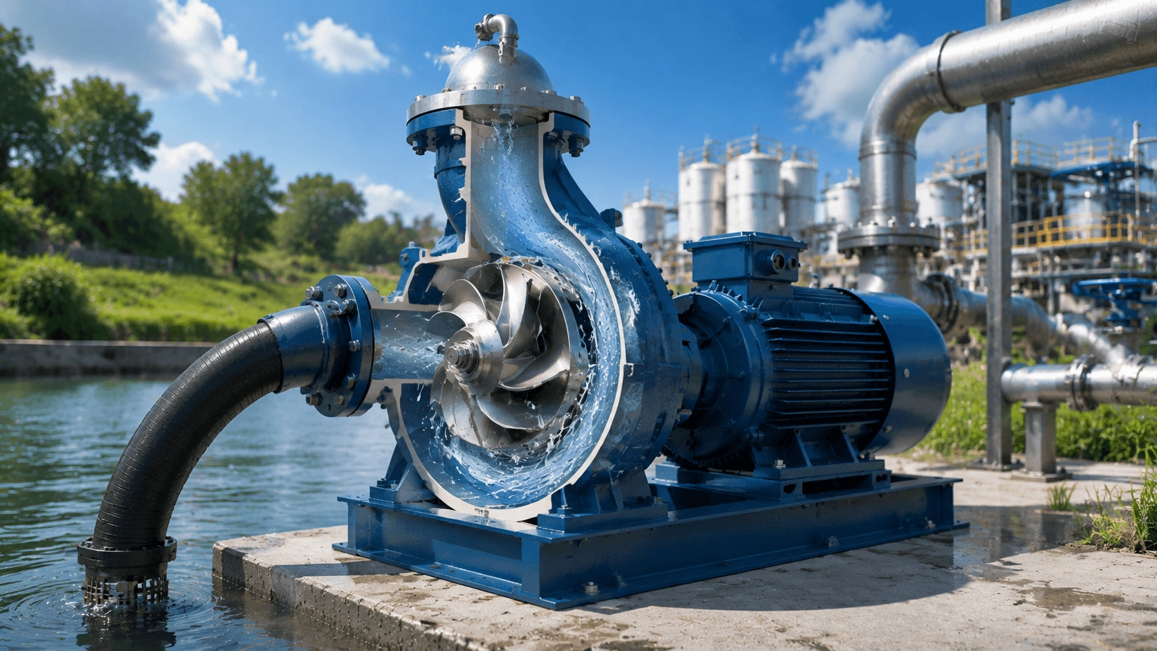
A comprehensive technical guide covering self-priming centrifugal pump operating principles, priming mechanisms, NPSH analysis, suction lift limitations, sizing methodology, installation best practices, and key industrial applications.
Table of Contents
- Introduction
- What Is a Self-Priming Centrifugal Pump?
- Working Principle & Priming Mechanism
- Key Components & Construction
- Performance Parameters & Engineering Formulas
- Types of Self-Priming Centrifugal Pumps
- Applications Across Industries
- Selection Guide & Sizing Calculations
- Installation, Operation & Maintenance Best Practices
- Troubleshooting Common Issues
- Advanced Considerations
- Conclusion
Introduction
In fluid-handling systems where the pump is positioned above the liquid source, the ability to evacuate air and establish suction without external priming assistance is not merely a convenience—it is an operational necessity. The self-priming centrifugal pump occupies a distinctive and critical position within the pump industry, effectively bridging the gap between standard centrifugal pumps, which require flooded suction, and positive-displacement pumps, which can handle air but at substantially higher cost and lower volumetric flow rates.
This comprehensive guide examines the engineering principles, performance characteristics, and application-specific considerations governing self-priming centrifugal pumps. Whether the objective is to size a new system, troubleshoot an existing installation, or evaluate competing pump technologies for a capital project, this article provides the technical depth required for informed, defensible engineering decisions.
1. What Is a Self-Priming Centrifugal Pump?
A self-priming centrifugal pump is a dynamic machine capable of automatically evacuating air from the suction line and generating the vacuum necessary to draw liquid into the pump casing, even when the pump is installed above the liquid level. Unlike conventional centrifugal pumps, which require the casing to be manually flooded with liquid prior to each startup, self-priming pumps retain a predetermined volume of liquid within a specially designed priming chamber, thereby enabling automatic repriming following the initial fill.
Core Advantages
| Advantage | Technical Explanation |
|---|---|
| Above-Ground Installation | Eliminates the need for submersible pumps, underground pump pits, or flooded-suction arrangements |
| Air-Handling Capability | Tolerates entrained air or gas concentrations of up to 15–20% by volume without loss of prime |
| Dry-Run Tolerance | Retained priming liquid provides temporary lubrication and cooling during the priming sequence |
| Simplified System Design | Removes the requirement for foot valves, external vacuum systems, or manual priming apparatus |
| Automatic Restart | Reprimes autonomously after power interruptions, dry-running events, or planned shutdowns |
2. Working Principle & Priming Mechanism
The self-priming capability is achieved through a recirculating priming cycle that separates entrained air from the liquid, evacuates the air through the discharge, and retains the liquid within the pump for continued operation.
The Priming Cycle (Step-by-Step)
- Initial Fill – The priming chamber (typically the volute casing or an external reservoir) is filled with liquid during first commissioning or remains filled from the preceding operating cycle.
- Air Evacuation – Upon startup, the impeller rotates and creates a partial vacuum at the impeller eye. The air–liquid mixture from the suction line enters the pump. The geometry of the priming chamber directs this mixture through a controlled recirculation path.
- Air–Liquid Separation – Owing to the substantial density differential, air separates from the liquid and is discharged through the pump outlet, while the heavier liquid returns to the priming chamber under gravity or via a dedicated recirculation port.
- Suction Establishment – As air is progressively evacuated from the suction line, the vacuum at the impeller eye deepens, drawing additional liquid upward until the suction line is fully primed and steady-state pumping commences.
Key Design Features Enabling Self-Priming
- Large priming-chamber volume (typically 2–3× the displacement volume per revolution)
- Internal recirculation port connecting the discharge region to the impeller eye
- Diffuser or separation channel to facilitate air–liquid disengagement
- Non-return valve or close-clearance impeller design to minimise backflow and retain priming liquid
3. Key Components & Construction
| Component | Function | Typical Material Options |
|---|---|---|
| Impeller | Converts mechanical shaft energy into fluid kinetic energy | Cast iron, bronze, 316 SS, CD4MCu |
| Volute / Priming Chamber | Collects fluid, converts velocity head to pressure, retains priming liquid | Cast iron, 316 SS, duplex stainless steel |
| Mechanical Seal | Prevents leakage at the shaft penetration; must withstand transient dry-running during priming | Carbon/Ceramic, SiC/SiC, PTFE-wedge |
| Shaft | Transmits torque from the driver to the impeller | AISI 4140 steel, 316 SS, 17-4 PH |
| Wear Ring | Maintains impeller-to-casing clearance; protects the casing from erosion | Bronze, stainless steel, PTFE |
| Recirculation Port | Channels liquid back to the impeller eye during the priming cycle | Integral to the casing casting |
Impeller Configurations
Self-priming pumps typically employ one of three impeller geometries, selected according to the nature of the pumped fluid:
- Closed Impeller – Highest hydraulic efficiency; suited to clean liquids; requires wear rings to maintain clearance.
- Semi-Open Impeller – Accommodates moderate solids and stringy materials; moderate efficiency; clearance is adjustable via shimming.
- Open (Vortex) Impeller – Maximum solids-handling capability; lowest hydraulic efficiency; minimal clogging risk.
4. Performance Parameters & Engineering Formulas
A rigorous understanding of the hydraulic and thermodynamic behaviour of self-priming pumps requires familiarity with the following fundamental performance relationships. All formulas below are presented in plain-text format for maximum compatibility.
4.1 Basic Hydraulic Equations
Total Dynamic Head (TDH):
H_total = H_static + H_friction + H_velocity + H_pressure
Hydraulic Power:
P_hydraulic (kW) = (rho * g * Q * H) / 1000
Where:
- rho = Fluid density (kg/m³)
- g = Gravitational acceleration (9.81 m/s²)
- Q = Flow rate (m³/s)
- H = Total dynamic head (m)
Brake (Input) Power:
P_brake (kW) = P_hydraulic / eta_pump
Where:
- eta_pump = Pump hydraulic efficiency (decimal)
4.2 Affinity Laws (Pump Scaling)
| Variable | Speed Change (n1 → n2) | Diameter Change (D1 → D2) |
|---|---|---|
| Flow Rate | Q2 = Q1 * (n2 / n1) | Q2 = Q1 * (D2 / D1) |
| Head | H2 = H1 * (n2 / n1)^2 | H2 = H1 * (D2 / D1)^2 |
| Power | P2 = P1 * (n2 / n1)^3 | P2 = P1 * (D2 / D1)^3 |
4.3 Net Positive Suction Head (NPSH)
NPSH analysis is of particular importance for self-priming pumps because the suction lift inherently creates negative gauge pressure at the impeller eye.
Available NPSH:
NPSHa = ((P_atm - P_v) / (rho * g)) - H_static_suction - H_friction_suction
Where:
- P_atm = Atmospheric pressure (Pa)
- P_v = Fluid vapour pressure (Pa)
- H_static_suction = Static suction lift (m, positive value for lift)
- H_friction_suction = Friction losses in suction line (m)
Design criterion: NPSHa >= NPSHr + 0.5 to 1.0 m
4.4 Suction Lift & Atmospheric Pressure
The theoretical maximum suction lift at mean sea level is approximately 10.33 m (one standard atmosphere). In practice:
H_lift_max ≈ 10.33 - NPSHr - H_friction - H_safety
Practical suction-lift limits for self-priming centrifugal pumps range from 4 m to 8 m, depending on pump geometry, liquid temperature, vapour pressure, and site altitude.
4.5 Priming Time Estimation
t_prime (min) = V_suction (m³) / Q_air (m³/min)
| Suction-Line Length | Typical Priming Time |
|---|---|
| Short (< 5 m) | 30 – 90 seconds |
| Medium (5 – 15 m) | 2 – 5 minutes |
| Long (> 15 m) | 5 – 10+ minutes |
4.6 Specific Speed (Ns)
Ns = (n * sqrt(Q)) / (H^0.75)
Where (metric units):
- n = Rotational speed (RPM)
- Q = Flow rate (m³/h)
- H = Head per stage (m)
| Ns Range (Metric) | Impeller Type | Typical Application |
|---|---|---|
| 10 – 50 | Radial, narrow passage | High head, low flow |
| 50 – 100 | Francis / mixed flow | Medium head, medium flow |
| 100 – 200 | Mixed flow | Medium head, high flow |
| > 200 | Axial / propeller | Low head, very high flow |
5. Types of Self-Priming Centrifugal Pumps
5.1 Comparison of Self-Priming Technologies
| Type | Priming Method | Max Suction Lift | Air Handling | Efficiency | Typical Applications |
|---|---|---|---|---|---|
| Liquid Ring | Liquid ring creates seal and compression | 8 – 9 m | Excellent (≤ 50% gas) | 40 – 55% | Vacuum extraction, chemical processing |
| Side Channel (Regenerative) | Multiple energy impulses in side channel | 7 – 8 m | Very good | 35 – 50% | LPG transfer, boiler feed, volatile liquids |
| Standard Self-Priming (Recirculation) | Recirculating liquid in volute | 5 – 8 m | Good (15 – 20% gas) | 55 – 75% | Water transfer, dewatering, irrigation |
| Vacuum-Assisted | External vacuum pump / priming system | 8 – 9 m | Excellent | 60 – 80% | High suction lift, large municipal systems |
| Ejector-Primed | Jet pump creates initial vacuum | 6 – 8 m | Moderate | 30 – 45% | Shallow wells, small domestic systems |
5.2 Standard Recirculation-Type (Most Common)
The recirculation-type design dominates industrial and municipal applications. The pump casing incorporates three essential features:
- A reservoir or enlarged volute that retains priming liquid between operating cycles.
- A recirculation port directing liquid back to the impeller eye during the priming sequence.
- An air-separation chamber in which entrained air bubbles rise and are discharged through the outlet.
Two principal sub-types exist:
- Internal recirculation – Compact, integrated design; suited to space-constrained installations.
- External recirculation – Separable priming loop; facilitates inspection and maintenance; provides visible confirmation of priming status.
6. Applications Across Industries
6.1 Industry-Specific Applications
| Industry | Representative Applications | Key Requirements |
|---|---|---|
| Municipal Water & Wastewater | Raw-water intake, booster stations, sewage lift | Reliable priming, solids handling, corrosion resistance |
| Construction & Mining | Dewatering, slurry transfer, sump pumping | Robust construction, high abrasion resistance, portability |
| Agriculture | Irrigation, field drainage, livestock watering | High flow rates, debris tolerance, cost efficiency |
| Marine | Bilge pumping, ballast transfer, deck wash-down | Compact footprint, seawater corrosion resistance, vibration tolerance |
| Chemical Processing | Acid transfer, solvent circulation, tanker loading/unloading | Material compatibility (alloys, fluoropolymers), seal integrity |
| Food & Beverage | CIP systems, ingredient transfer, process wastewater | Sanitary construction, FDA/EC 1935-compliant materials |
| Oil & Gas | Tank-farm transfer, pipeline boosting, produced-water handling | API compliance, explosion-proof motors, NACE MR0175 materials |
6.2 Fluid-Compatibility Considerations
| Fluid Characteristic | Design Modification | Recommended Materials |
|---|---|---|
| Abrasive solids | Open / semi-open impeller; hardened wear surfaces | High-chrome iron, CD4MCu, rubber lining |
| Corrosive chemicals | Minimised metal contact; seal flush plans (Plan 52/53) | 316 SS, Alloy 20, Hastelloy, PVDF / PTFE |
| High temperature (> 120 °C) | Cooling jacket; high-temperature seal arrangement | Heat-resistant alloys, graphite / carbon seals |
| Viscous liquids (> 500 cSt) | Reduced rotational speed; enlarged impeller passages | Standard cast iron with adjusted clearances |
| Fibrous / stringy materials | Vortex impeller; optional cutter attachment | Cast iron with hardened leading edges |
7. Selection Guide & Sizing Calculations
7.1 Selection Checklist
- Define operating conditions – Flow rate (Q), total dynamic head (H), suction geometry (static lift, line length, pipe diameter), and fluid properties (temperature, specific gravity, viscosity, solids content).
- Determine NPSH availability – Calculate NPSHa; compare against the manufacturer's NPSHr curve; ensure a minimum margin of 0.5 m (1.0 m preferred).
- Evaluate priming requirements – Suction-line volume, maximum acceptable priming time, and frequency of anticipated dry-start events.
- Select materials of construction – Based on fluid corrosivity, abrasiveness, operating temperature, and pressure rating.
- Specify drive and controls – Motor sizing with a service factor of ≥ 1.15; VFD compatibility where variable flow is required; control logic for automatic priming monitoring and dry-run protection.
7.2 Worked Sizing Example
Application: Construction-site dewatering
Duty: Q = 50 m³/h · H = 25 m · Suction lift = 5 m · Suction line: 80 m of DN 100 pipe
| Step | Calculation | Result |
|---|---|---|
| 1 – NPSH Verification | NPSHa = 10.33 - 0.24 (vapour) - 5.0 (lift) - 2.5 (friction) | NPSHa ≈ 2.59 m → select pump with NPSHr ≤ 1.5 m at 50 m³/h |
| 2 – Hydraulic Power | P = (1000 * 9.81 * (50/3600) * 25) / (1000 * 0.70) | P_brake ≈ 4.87 kW |
| 3 – Motor Selection | Apply 1.15 service factor → 4.87 * 1.15 ≈ 5.6 kW | Select 7.5 kW (10 HP) standard frame motor |
| 4 – Priming Time Check | V_suction ≈ 0.628 m³; Q_air ≈ 0.15 m³/min | t_prime ≈ 4.2 min (acceptable) |
8. Installation, Operation & Maintenance Best Practices
8.1 Installation Guidelines
| Parameter | Best Practice | Common Error to Avoid |
|---|---|---|
| Suction Line | Shortest practical length; pipe diameter ≥ pump suction nozzle | Undersized suction pipe causing excessive friction loss |
| Suction Strainer | Install only when necessary; size for 3–4× the flow area | Clogged strainer inducing cavitation |
| Foot Valve | Generally not required (defeats the self-priming purpose) | Unnecessary foot valve adding friction and maintenance |
| Discharge Check Valve | Install immediately downstream to prevent backflow and water hammer | Omitted check valve causing impeller back-spin and seal damage |
| Foundation | Rigid, level base with epoxy grouting; shaft alignment ≤ 0.05 mm TIR | Flexible or uneven mounting causing misalignment and vibration |
| Piping Support | Independently support suction and discharge piping | Pipe strain transmitted to pump flanges, leading to bearing failure |
8.2 Initial Startup Procedure
- Fill the priming chamber with clean liquid through the designated fill port or via the discharge connection.
- Verify that the direction of rotation matches the arrow cast or labelled on the casing.
- Open the discharge valve to approximately 10–20% to prevent dead-heading during the priming phase.
- Energise the motor and monitor priming time against the expected value.
- Once priming is confirmed (steady discharge pressure), gradually open the discharge valve to the operating position.
- Record baseline operating parameters: discharge pressure, motor current, vibration levels, and bearing temperature.
8.3 Preventive Maintenance Schedule
| Interval | Inspection Item | Required Action |
|---|---|---|
| Daily | Leakage, vibration, temperature, abnormal noise | Visual and auditory inspection; address anomalies immediately |
| Weekly | Seal condition, bearing temperature, coupling alignment | Record baseline data; tighten fasteners as necessary |
| Monthly | Strainer condition, lubrication level, motor current draw | Clean strainer; replenish grease per manufacturer specification |
| Quarterly | Impeller clearance, wear-ring condition, seal flush system | Adjust impeller clearance; inspect and replace wear components |
| Annually | Complete teardown inspection, hydrostatic test, performance verification | Replace seals, bearings, and wear rings as warranted; verify against published curve |
9. Troubleshooting Common Issues
| Symptom | Probable Cause | Corrective Action |
|---|---|---|
| Pump fails to prime | Insufficient liquid in priming chamber; air leak in suction line; blocked recirculation port | Refill priming chamber; inspect gaskets, fittings, and shaft seal for leaks; clear recirculation passage |
| Excessive priming time | Suction lift exceeds design limit; suction-line leak; worn impeller or casing | Reduce static lift or select a larger pump; pressure-test suction line; inspect and restore internal clearances |
| Loss of prime during operation | Air ingress through suction leak; vortexing at suction source; excessive entrained air in fluid | Seal all suction joints; increase submergence depth; install a vortex breaker at the suction inlet |
| Low flow / pressure | Worn impeller; incorrect rotation; clogged impeller passages; speed below rated | Replace impeller; verify motor wiring phasing; clean impeller; check VFD frequency setting |
| Cavitation noise / damage | NPSHa < NPSHr; suction restriction; liquid temperature too high | Increase suction pipe diameter; reduce lift; cool liquid; select a lower-NPSH pump model |
| Excessive vibration | Coupling misalignment; impeller imbalance; bearing wear; cavitation | Realign coupling to ≤ 0.05 mm TIR; dynamically balance impeller; replace bearings; resolve root cavitation cause |
| Seal leakage | Prolonged dry running; seal-face damage; excessive vibration; improper installation | Ensure priming chamber always contains liquid; replace mechanical seal; resolve vibration; reinstall per manufacturer procedure |
| Motor overload | Fluid specific gravity exceeds design; speed too high; mechanical binding; impeller rubbing casing | Verify fluid properties; check VFD output; inspect bearings and internal clearances |
10. Advanced Considerations
10.1 Variable-Frequency Drive (VFD) Operation
- Minimum operating speed: Typically 30–40% of rated speed is required to generate sufficient centrifugal force for effective priming.
- Acceleration profile: Excessively slow ramps may prevent proper priming; a 3–5 second acceleration ramp is generally recommended.
- NPSH at reduced speed: Because NPSHr decreases with the square of speed, suction performance improves at lower flows—a useful characteristic for variable-demand systems.
10.2 Parallel Pump Operation
- Ensure that all parallel pumps have identical or closely matched performance curves to prevent one pump operating at shut-off while the other carries the full load.
- Install individual check valves on each pump discharge to prevent backflow through idle units.
- Consider staggered startup sequencing to avoid simultaneous priming demand on a shared suction header.
10.3 Environmental & Regulatory Compliance
| Regulation / Standard | Relevance to Self-Priming Pumps |
|---|---|
| EPA Clean Water Act | Discharge limitations; material-leaching standards for potable-water service |
| ATEX / IECEx | Explosion-proof motor and enclosure requirements for flammable or combustible liquids |
| API 610 / API 685 | Refinery and petrochemical pump design and sealing standards |
| ISO 5199 | Technical specifications for chemical-process pumps |
| EU Ecodesign (Reg. 547/2012) | Minimum energy-efficiency requirements for water pumps sold in the European market |
Conclusion
The self-priming centrifugal pump represents a mature yet continuously evolving technology that addresses one of fluid handling's most persistent engineering challenges: lifting liquid from below the pump centreline without external priming assistance. Success in specification, installation, and long-term operation depends upon the rigorous application of hydraulic engineering principles—from NPSH analysis and affinity-law scaling to material selection and structured maintenance planning.
By understanding the priming mechanism, respecting the physical limits imposed by atmospheric pressure and vapour pressure, and matching pump construction to the specific properties of the pumped fluid, engineers can deploy self-priming centrifugal pumps with confidence across municipal, industrial, agricultural, and marine applications. The formulas, comparative tables, and procedural guidelines presented in this article provide the foundational knowledge necessary to specify, install, and maintain systems that deliver reliable, efficient service for decades.
Document last reviewed: August 2026. For project-specific calculations, always verify results against the pump manufacturer's certified performance data and applicable local codes.