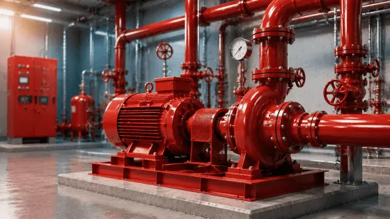
1. Introduction and Fundamental Role
A fire pump is a stationary pump dedicated to providing water at the flow rates and pressures required by fire protection systems. Unlike general-purpose pumps, fire pumps are subject to stringent listing requirements by recognized testing laboratories (UL, FM) and their installation, operation, and maintenance are governed by NFPA 20, Standard for the Installation of Stationary Pumps for Fire Protection.
The fundamental purpose of a fire pump is to augment the available water supply pressure when the source pressure is insufficient to meet the hydraulic demands of sprinkler systems, standpipe systems, or hose streams. When a fire protection system activates, waterflow causes a pressure drop that triggers the pump controller, automatically starting the pump to restore and maintain adequate pressure.
2. Centrifugal Pump Operating Principles
A centrifugal fire pump converts the mechanical energy of a rotating impeller into hydraulic energy. Fluid enters the impeller eye axially, is accelerated radially by the curved impeller vanes, and is discharged into the volute casing at high velocity. The volute's expanding cross-section converts kinetic energy into pressure energy.
The theoretical head developed by a centrifugal pump is described by Euler's pump equation:
H_theoretical = (u₂ · c_u2 - u₁ · c_u1) / g
Where:
- u₂ = Peripheral velocity at impeller outlet (ft/s)
- c_u2 = Tangential component of absolute velocity at outlet (ft/s)
- u₁ = Peripheral velocity at impeller inlet (ft/s)
- c_u1 = Tangential component of absolute velocity at inlet (ft/s)
- g = Gravitational acceleration (32.2 ft/s²)
In practice, hydraulic losses reduce the actual head:
H_actual = η_h · H_theoretical
Where η_h is the hydraulic efficiency, typically 80–90% for well-designed fire pumps.
3. Types of Fire Pumps
3.1 Horizontal End-Suction Pumps
Fluid enters axially at one end of the impeller and exits radially through a volute casing. The impeller is typically single-suction, overhung on the shaft.
| Characteristic | Specification |
|---|---|
| Flow Range | 25–1,500 GPM |
| Head Range | 40–300 ft |
| Efficiency | 70–82% |
| Footprint | Compact |
| Maintenance | Impeller access requires pump removal or casing split |
| Cost | Lowest initial cost |
End-suction pumps are ideal for small to medium commercial buildings and retrofit applications.
3.2 Horizontal Split-Case Pumps
The casing is split horizontally along the shaft centerline. The impeller is double-suction, balancing axial thrust forces. Bearings support the shaft on both sides.
| Characteristic | Specification |
|---|---|
| Flow Range | 400–5,000 GPM |
| Head Range | 50–400 ft |
| Efficiency | 82–88% |
| Footprint | Moderate to large |
| Maintenance | Top half casing removes without disturbing piping |
| Cost | Moderate |
Split-case pumps are the dominant choice for large commercial and industrial systems.
3.3 Vertical Turbine Pumps
A vertical shaft with multiple impeller stages submerged in the water source. The motor is mounted above the discharge head.
| Characteristic | Specification |
|---|---|
| Flow Range | 250–5,000+ GPM |
| Head Range | 100–800+ ft |
| Efficiency | 75–85% |
| Footprint | Small floor area |
| Maintenance | Requires pulling entire bowl assembly |
| Cost | Moderate to high |
Vertical turbine pumps are essential when the water source is below grade.
4. Performance Requirements and Acceptance Criteria
Fire pumps must meet strict performance criteria established by UL 448, FM 1319, and ANSI/HI 14.6.
4.1 The Three Critical Test Points
| Test Point | Flow Condition | Head Requirement |
|---|---|---|
| Churn (Shut-off) | 0 GPM | ≤ 140% of rated head |
| Rated Point | 100% of rated capacity | Within ±5% of catalog value |
| Overload | 150% of rated capacity | ≥ 65% of rated head |
4.2 Mathematical Verification
For a pump rated at 1,000 GPM at 100 ft head:
Churn head limit:
H_churn,max = 1.40 × 100 = 140 ft
Overload head minimum:
H_150%,min = 0.65 × 100 = 65 ft
Overload flow:
Q_150% = 1.50 × 1000 = 1500 GPM
4.3 Power Requirements
The driver must be capable of delivering peak power:
P_peak = (Q_150% × H_150% × SG) / (3960 × η_pump)
For the example pump at 1,500 GPM and 65 ft, assuming 75% efficiency:
P_peak = (1500 × 65 × 1.0) / (3960 × 0.75) = 32.8 HP
NFPA 20 requires the driver to be rated for at least this peak power.
5. Driver Types
5.1 Electric Motors
| Parameter | Requirement |
|---|---|
| Voltage | 208V, 480V, or 600V, 3-phase |
| Starting Method | Full-voltage (DOL) or reduced-voltage |
| Cooling | Minimum 40°C ambient rating |
| Protection | No thermal overload relays |
Critical Design Note: NFPA 20 prohibits thermal overload protection on fire pump motors. The pump must be allowed to run even if overheating.
5.2 Diesel Engines
| Parameter | Requirement |
|---|---|
| Fuel Supply | On-site tank for 8 hours at rated load |
| Starting System | Two battery sets with automatic alternation |
| Cooling | Heat exchanger or radiator |
| Speed | Must reach rated speed within 20 seconds |
5.3 Driver Selection Formula
P_driver ≥ (P_peak / η_transmission) × SF
Where:
- P_peak = Peak pump brake horsepower
- η_transmission = Coupling efficiency (0.97–0.99)
- SF = Service factor (1.0 for electric, 1.15 for diesel)
6. Suction Piping Design and NPSH Analysis
6.1 Suction Piping Requirements (NFPA 20)
| Requirement | Specification |
|---|---|
| Pipe Size | ≥ pump suction flange size |
| Straight Run | ≥ 10 pipe diameters before flange |
| Eccentric Reducer | Flat side up |
| Elbows | Long-radius; none within 10 diameters of flange |
6.2 NPSH Calculation
NPSH_a = h_atm ± h_static - h_f - h_vp
Example 1: Elevated Tank
- Tank water level: 20 ft above pump
- Suction friction: 2 ft
- NPSH_a = 33.9 + 20 - 2 - 0.8 = 51.1 ft
Example 2: Suction Lift
- Water level: 8 ft below pump
- Suction friction: 4 ft
- NPSH_a = 33.9 - 8 - 4 - 0.8 = 21.1 ft
7. Discharge Piping and Accessories
| Component | Location | Function |
|---|---|---|
| Flexible Coupling | Both sides of pump | Accommodates thermal expansion |
| OS&Y Gate Valve | Immediately after pump | Isolates pump for maintenance |
| Swing Check Valve | Between pump and discharge valve | Prevents backflow |
| Main Relief Valve | Downstream of check valve | Limits pressure to ≤ 140% rated |
| Concentric Increaser | After relief valve | Smooth velocity transition |
7.1 Circulation Relief Valve
A circulation relief valve (minimum ¾ inch NPT) prevents overheating during churn conditions. Without it:
- Heat input: 254,500 BTU/hr for 100 HP pump
- Temperature rise: approximately 50°F per minute
8. Pump Controllers
8.1 Controller Types
| Type | Application | Key Features |
|---|---|---|
| Electric | Motor-driven pumps | Automatic start, manual override, phase reversal protection |
| Diesel Engine | Engine-driven pumps | Battery monitoring, fuel level, overspeed governor |
| Transfer Switch | Dual-source electric | Normal/emergency power transfer, mechanical interlock |
8.2 Pressure Switch Settings
| Setting | Typical Value |
|---|---|
| Main Pump Start | Churn pressure − 10 psi |
| Main Pump Stop | Manual only |
| Jockey Pump Start | Churn pressure − 5 psi |
| Jockey Pump Stop | Churn pressure + 5 psi |
9. Field Acceptance Testing
9.1 Test Procedure
| Step | Flow Rate | Acceptance Criteria |
|---|---|---|
| Churn Test | 0 GPM | Head ≤ 140% of rated; no excessive vibration |
| Rated Flow | 100% | Head within ±5% of catalog; current ≤ nameplate |
| Overload | 150% | Head ≥ 65% of rated; current ≤ service factor |
9.2 Documentation
The acceptance test report must include pump and driver specifications, pressure and flow measurements at each test point, plot against manufacturer's certified curve, and signatures from installer, owner, and AHJ.
10. Maintenance and Testing (NFPA 25)
| Interval | Procedure |
|---|---|
| Weekly | No-flow test (electric) or no-load run (diesel) |
| Monthly | Churn test: 10 minutes at no-flow |
| Quarterly | Flow test at rated capacity (if permitted) |
| Annually | Full flow test at 100% and 150% rated |
| 5-Year | Internal inspection: casing, impeller, wear rings |
11. Common Design Errors
11.1 Oversized Pump
An oversized pump operates far right of BEP, causing low efficiency and high power consumption.
- Diagnostic: At rated demand, pump operates at > 125% of catalog flow.
- Correction: Trim impeller or install bypass line.
11.2 Undersized Suction Piping
Creates excessive inlet velocity and friction loss, reducing NPSH_a.
- Diagnostic: Abnormal pressure drop at high flow; noise and vibration.
- Correction: Increase suction pipe diameter.
11.3 Incorrect Pressure Settings
If main pump start is set too high, pump starts on minor fluctuations.
- Diagnostic: Frequent starts (> once per week outside testing).
- Correction: Recalibrate per NFPA 20 hierarchy.
12. Regulatory Framework
| Standard | Scope |
|---|---|
| NFPA 20 | Installation of stationary fire pumps |
| NFPA 13 | Sprinkler system hydraulic demands |
| NFPA 14 | Standpipe and hose system requirements |
| NFPA 24 | Private fire service mains |
| NFPA 25 | Inspection, testing, and maintenance |
| UL 448 | Fire pump listing requirements |
| FM 1319 | Factory Mutual approval standard |
| ANSI/HI 14.6 | Pump performance testing |
13. Advanced Topics
13.1 Specific Speed and Impeller Design
Specific speed is a dimensionless parameter that characterizes pump geometry:
N_s = (N × √Q) / H^0.75
Where:
- N = Rotational speed (RPM)
- Q = Flow at BEP (GPM)
- H = Head at BEP (ft)
| N_s Range | Impeller Type | Characteristics |
|---|---|---|
| 500–2,000 | Radial flow | Narrow, large diameter; high head, low flow |
| 2,000–5,000 | Mixed flow | Moderate width and diameter; balanced |
| 5,000–15,000 | Axial flow | Wide, small diameter; low head, high flow |
13.2 Affinity Laws
For speed changes on the same pump:
Q₂/Q₁ = N₂/N₁, H₂/H₁ = (N₂/N₁)², P₂/P₁ = (N₂/N₁)³
A 20% speed increase yields 20% more flow, 44% more head, and 73% more power.
13.3 Pump Room Design
| Requirement | NFPA 20 Specification |
|---|---|
| Clearance | 3 ft on all sides of pump assembly |
| Floor Drain | Required for test water and relief discharge |
| Ventilation | 6 air changes per hour minimum |
| Door Width | ≥ largest component (typically 4 ft) |
| Ceiling Height | ≥ 8 ft; ≥ 2 ft above tallest component |
| Heating | Required if ambient < 40°F; no open flame |
14. Summary and Key Takeaways
- Fire pumps are specialized, listed equipment. Only UL-listed or FM-approved pumps may be used.
- Performance acceptance is binary. The pump must satisfy: churn ≤ 140%, rated point ±5%, and 150% flow ≥ 65% of rated head.
- Suction design determines pump life. Proper NPSH margin, straight runs, and air-free piping prevent cavitation.
- Driver selection includes safety margins. Diesel engines require 15% oversizing; electric motors run without thermal protection.
- Controllers are life-safety devices. They must start automatically and cannot be programmed to stop automatically.
- Testing validates design. Annual full-flow tests and 5-year internal inspections ensure continued capability.