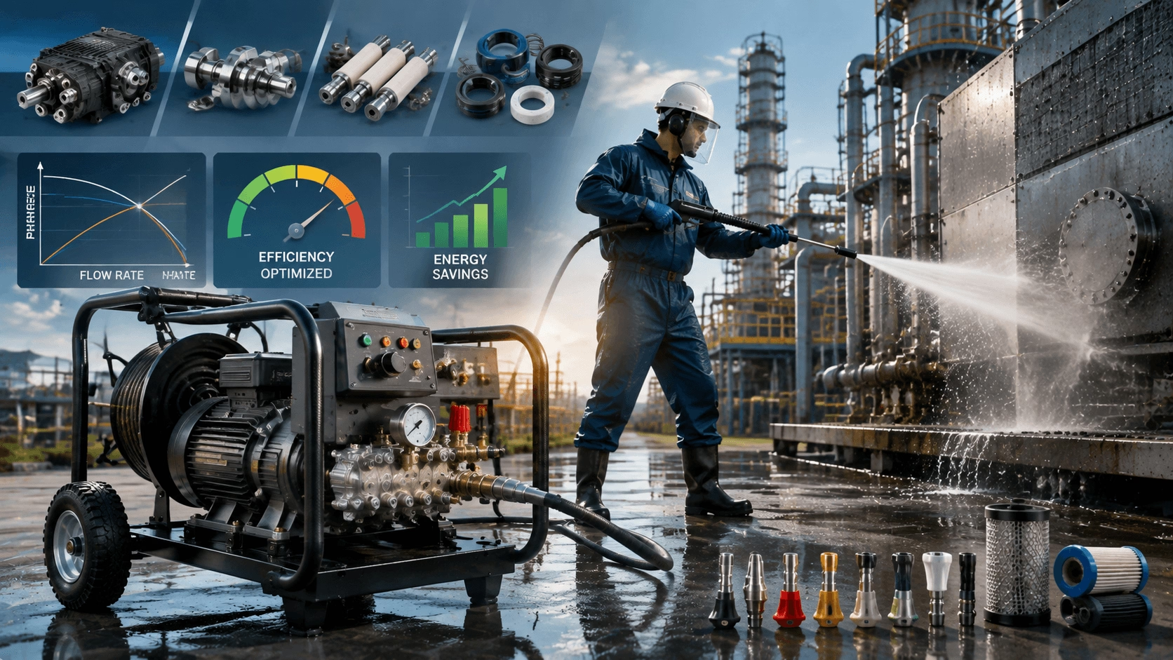
The Engineering Mechanics and Performance Metrics of Industrial High-Pressure Washers
A technical analysis of industrial high-pressure cleaning systems covering pump architecture, hydraulic dynamics, material science, energy efficiency, and quantifiable performance metrics. Essential reference for engineers, procurement specialists, and facility managers specifying heavy-duty cleaning equipment.
Introduction: Engineering Precision Over Raw Power
In industrial maintenance and facility management, high-pressure washers are critical assets for operational efficiency, hygiene compliance, and asset preservation. However, cleaning efficacy is not merely a function of maximum pressure rating; it results from precise hydraulic engineering, optimal component integration, and application-matched performance characteristics.
For procurement specialists and facility managers, selecting equipment based solely on headline specifications leads to suboptimal outcomes—either inadequate cleaning performance, excessive surface damage, premature equipment failure, or inflated operating costs. This guide provides a rigorous technical framework for evaluating industrial high-pressure washers, enabling evidence-based specification that aligns engineering capability with operational demand.
Pump Architecture and Material Science
The pump is the primary determinant of system reliability, performance stability, and service life. Industrial applications demand architectures engineered for continuous duty, thermal resilience, and wear resistance.
Pump Design Topologies
| Architecture | Operating Principle | Duty Cycle Suitability | Key Characteristics |
|---|---|---|---|
| Axial Cam (Wobble Plate) | Pistons driven by angled swash plate; compact inline design | Light commercial / intermittent (<500 hrs/yr) | Lower cost; limited heat dissipation; shorter bearing life; adequate for <20 MPa |
| Radial Plunger (Crankshaft) | Pistons arranged radially around crankshaft; balanced reciprocating forces | Heavy industrial / continuous (>2,000 hrs/yr) | Superior thermal management; higher volumetric efficiency; extended bearing L10 life; standard for >20 MPa continuous duty |
| Triplex vs. Quintuplex | 3 vs. 5 plungers per revolution | Triplex: general industrial; Quintuplex: ultra-high flow/low pulsation | Quintuplex reduces flow ripple by ~60%; smoother operation; lower vibration; preferred for sensitive surfaces and precision cleaning |
Selection Guidance: For any application exceeding 4 hours/day continuous operation or pressures above 25 MPa, radial plunger architecture is non-negotiable. Axial cam pumps in these conditions experience accelerated seal degradation, cavitation-induced pitting, and catastrophic bearing failure.
Critical Material Specifications
| Component | Standard Material | Premium Upgrade | Engineering Benefit |
|---|---|---|---|
| Pump Head/Manifold | Forged brass or cast stainless steel | Duplex stainless steel / nickel-aluminum bronze | Corrosion resistance; fatigue strength; compatibility with aggressive chemicals and seawater |
| Plungers | Hardened steel or chrome-plated steel | Solid ceramic (zirconia/alumina) | Ceramic reduces friction coefficient by 40–60%; near-zero wear in abrasive service; eliminates corrosion; extends seal life 3–5× |
| Valves & Seats | Stainless steel | Tungsten carbide or ceramic composite | Erosion resistance in sandy/particulate-laden water; maintains volumetric efficiency over extended intervals |
| Seals/Packing | NBR or FKM elastomers | PTFE-based composite with spring energization | Chemical compatibility; temperature range −40°C to +260°C; self-compensating wear; reduced leakage |
| Bearings | Standard deep groove ball | Tapered roller or angular contact; oversized rating | Handles combined radial/axial loads from plunger forces; extended L10 life under continuous shock loading |
Thermal Management Considerations
Continuous-duty industrial pumps generate significant waste heat through hydraulic inefficiency and mechanical friction. Key design features include:
- Integrated Cooling Channels: Water-jacketed pump heads dissipate heat directly to process fluid
- Oversized Crankcase Oil Reservoir: Increases thermal mass and residence time for heat rejection
- External Oil Coolers: Mandatory for ambient temperatures >40°C or enclosed installations
- Thermal Relief Valves: Protect seals and packing from overheating during bypass/deadhead conditions
Pressure-Flow Dynamics: The True Measure of Cleaning Efficacy
Debunking the Pressure-Only Fallacy
A persistent specification error is prioritizing maximum pressure (MPa/bar/psi) while neglecting flow rate (LPM/GPM). While pressure determines the impact force available to fracture contaminant adhesion bonds, flow rate governs the mass transport capacity required to evacuate dislodged debris from the work surface.
Insufficient flow at high pressure produces narrow, ineffective spray patterns that clean slowly and risk substrate damage. Excessive flow at low pressure rinses efficiently but fails to break tenacious contamination bonds.
Cleaning Units (CU): Integrated Performance Metric
CU = Pressure (bar) × Flow Rate (LPM)
Or in imperial units:
CU = PSI × GPM
Cleaning Units provide a single scalar metric representing total hydraulic work capacity. However, CU alone is insufficient—the ratio of pressure to flow must match the specific soil-substrate combination.
Application-Matched Pressure-Flow Ratios
| Application Category | Recommended Pressure Range | Recommended Flow Range | Rationale |
|---|---|---|---|
| Light Surface Cleaning (dust, loose dirt, vehicles) | 7–15 MPa | 15–30 LPM | Low adhesion force; high flow maximizes coverage rate |
| General Industrial Degreasing (oil, grease, grime) | 15–25 MPa | 20–40 LPM | Moderate bond strength; balanced impact and rinse capacity |
| Heavy Contaminant Removal (paint, rust, scale, concrete) | 25–50 MPa | 15–30 LPM | High adhesion/cohesion; pressure-dominant for fracture |
| Surface Preparation (coating removal, profiling) | 50–100+ MPa | 10–25 LPM | Extreme bond strength; specialized nozzles; UHP classification |
| Large-Area Rinsing (tanks, floors, facades) | 10–20 MPa | 40–80+ LPM | Post-cleaning evacuation; flow-dominant for productivity |
Nozzle Hydraulics and Spray Pattern Optimization
Nozzle orifice size and geometry determine the pressure-flow operating point for a given pump:
Q = K × d² × √P
Where Q = flow rate, K = discharge coefficient, d = orifice diameter, P = pressure.
- Undersized Nozzle: Increases pressure beyond design point; reduces flow; risks pump overload and surface damage
- Oversized Nozzle: Reduces pressure below effective threshold; increases flow; wastes energy and water
- Correct Sizing: Matches pump BEP (Best Efficiency Point) to application requirements; consult manufacturer nozzle selection charts
Critical Note: Nozzle wear increases orifice diameter over time, progressively reducing pressure and shifting the operating point. Implement nozzle inspection/replacement schedules based on cumulative operating hours and water quality. A 10% orifice enlargement reduces pressure by approximately 20%.
Energy Efficiency and Power Source Selection
Energy consumption represents 60–80% of total lifecycle cost for industrial pressure washers. Power source selection and control technology directly determine operating economics and environmental footprint.
Power Source Comparison Matrix
| Parameter | Electric Motor | Diesel Engine | Gasoline Engine | Hydraulic Drive |
|---|---|---|---|---|
| Energy Conversion Efficiency | 85–95% | 30–40% | 25–35% | 70–85% (system-dependent) |
| Noise Level | 65–75 dB(A) | 85–95 dB(A) | 80–90 dB(A) | Variable (power unit remote) |
| Emissions | Zero at point of use | NOx, PM, CO₂; Tier 4/Stage V compliant | CO, HC, NOx; less regulated | Zero at point of use |
| Indoor Suitability | Excellent | Prohibited without ventilation/exhaust treatment | Prohibited | Excellent |
| Mobility | Limited (corded) or battery-constrained | Excellent | Good | Excellent (if mobile power unit) |
| Maintenance Intensity | Low | High (filters, fluids, emissions systems) | Medium-High | Medium |
| Best Application Profile | Indoor facilities, fixed stations, emission-regulated zones | Remote sites, heavy mobile duty, no grid access | Light mobile, intermittent outdoor use | Existing hydraulic power availability, hazardous areas |
Advanced Energy Management Technologies
| Technology | Function | Energy Savings Potential |
|---|---|---|
| Variable Speed Drive (VSD/VFD) | Modulates motor/pump speed to match real-time demand; eliminates unloaded bypass losses | 30–50% in variable-demand applications |
| Automatic Unloader with Bypass Recirculation | Diverts flow to low-pressure loop when trigger released; prevents deadhead heating | Reduces wasted energy during idle periods; protects pump |
| Load-Sensing Hydraulic Systems | Adjusts pump displacement to maintain pressure only as needed | 20–40% vs. fixed-displacement systems |
| High-Efficiency Motors (IE3/IE4) | Reduced electrical losses across load range | 5–15% vs. IE1/IE2 baseline |
| Heat Recovery Systems | Captures waste heat from engine/motor for water preheating | Improves cleaning efficacy; reduces fuel/electricity for heating |
Total Cost of Ownership (TCO) Modeling
When comparing alternatives, calculate 5-year TCO including:
- Capital acquisition cost
- Energy/fuel consumption at actual duty cycle
- Scheduled maintenance labor and parts
- Unscheduled repair frequency and downtime cost
- Consumables (nozzles, seals, filters, chemicals)
- Disposal/residual value
Electric systems typically achieve TCO parity with diesel within 18–36 months in fixed-installation applications despite higher initial cost, driven by energy and maintenance differentials.
Key Performance Metrics for Specification and Validation
| Metric | Definition | Measurement Method | Acceptance Benchmark |
|---|---|---|---|
| Rated Pressure | Maximum continuous operating pressure at rated flow | Calibrated gauge at pump outlet; ISO 9362 | Within ±5% of nameplate; stable under load |
| Rated Flow | Volumetric output at rated pressure and speed | Flow meter in discharge line; ISO 9362 | Within ±5% of nameplate; verify at multiple pressures |
| Volumetric Efficiency | Actual flow / theoretical displacement flow | Calculated from measured flow vs. geometric displacement | ≥90% new; ≥80% end-of-service-interval |
| Pressure Stability | Ripple amplitude and regulation accuracy | Oscilloscope/datalogger on pressure transducer | ≤5% ripple; ±3% regulation under variable load |
| Specific Energy Consumption | kWh per m³ cleaned or kWh per CU-hour | Energy meter + production tracking | Benchmark against industry standards; track trend |
| Mean Time Between Failures (MTBF) | Cumulative operating hours / number of functional failures | CMMS records; OEM warranty data | Application-dependent; >2,000 hrs for heavy industrial |
| Noise Emission | Sound power level per ISO 3744 | Standardized test environment | Compliance with local occupational exposure limits |
| Water Consumption Efficiency | Liters per m² cleaned at specified cleanliness level | Field measurement + visual/tactile verification | Minimize while achieving acceptance criteria |
Conclusion: Strategic Specification Through Technical Understanding
Selecting industrial high-pressure washing equipment is an engineering decision with multi-year operational and financial consequences. Success requires moving beyond marketing specifications to evaluate:
- Pump architecture and materials matched to duty cycle and fluid characteristics
- Pressure-flow ratios optimized for specific soil-substrate combinations, not maximum ratings
- Energy efficiency technologies justified by TCO analysis, not nominal power ratings
- Quantifiable performance metrics verified through testing and field validation
Investing in technically superior, application-matched equipment is not merely a capital expenditure—it is a strategic enabler of productivity, safety, compliance, and sustainable operational excellence.
Upgrade to Engineered Industrial High-Pressure Cleaning Systems
For custom-specified high-pressure washers featuring premium radial plunger pumps, ceramic components, optimized pressure-flow configurations, and advanced energy management systems:
📧 Request Engineering Consultation & Custom Proposal: [Contact Our Technical Team]
🌐 Product Portfolio & Technical Resources: www.cntecho.com
Titecho: Where hydraulic engineering meets industrial cleaning performance.