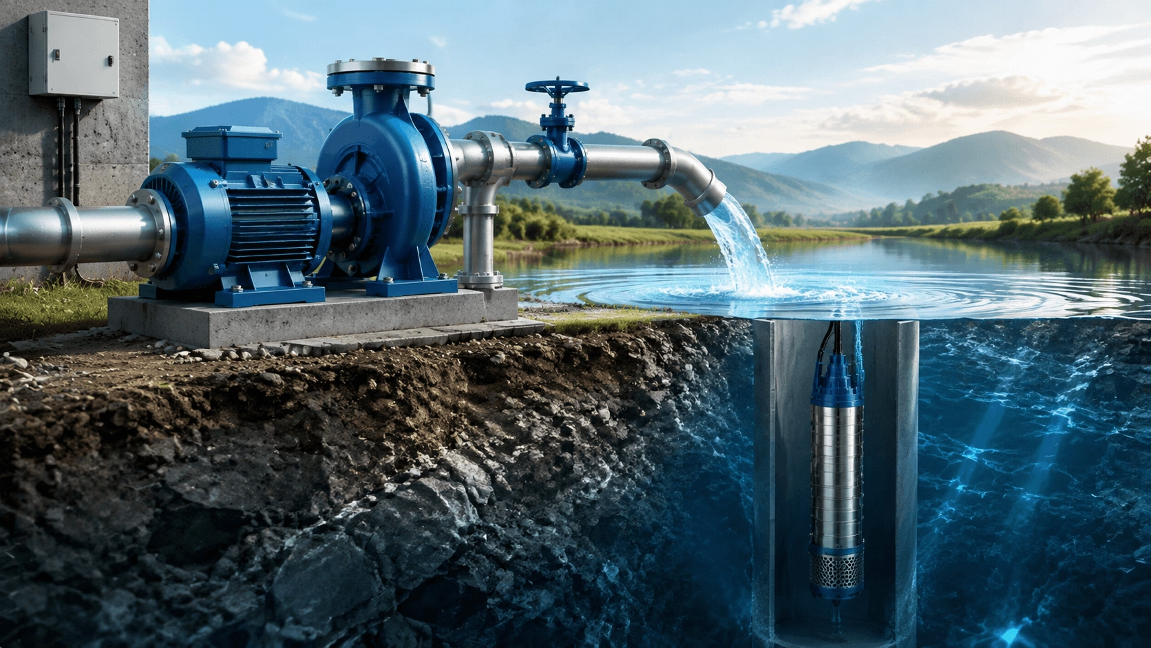
How Water Pumps Work: Centrifugal & Submersible Pump Principles
A comprehensive technical guide to water pump operating principles, hydraulic fundamentals, performance characterization, and selection methodology. Covers centrifugal, submersible, self-priming, and positive displacement technologies with expert insights from Titecho engineering.
Introduction to Pump Technology
Principles, Types & Performance for Water Applications
Water pumps rank among humanity’s most consequential engineered systems, enabling agricultural productivity, industrial development, municipal water supply, and habitation of otherwise uninhabitable regions. From ancient norias and Archimedean screws to modern multi-stage centrifugal and submersible systems, the fundamental engineering challenge remains unchanged: adding energy to a fluid to move it efficiently and reliably from one point to another.
This guide provides a rigorous technical exposition of contemporary water pump technology—covering hydraulic theory, operating mechanisms, performance curves, cavitation prevention, and systematic selection criteria—to support informed specification, operation, and maintenance decisions.
Fundamental Hydraulic Principles
All pumps function as energy-addition devices. They increase the mechanical energy of a fluid to overcome system resistance and achieve desired flow conditions.
Energy Forms in Fluid Systems
| Energy Type | Physical Expression | Practical Unit Conversion |
|---|---|---|
| Pressure Energy (Head) | Static pressure expressed as equivalent liquid column height | 1 m head ≈ 0.1 bar ≈ 1.45 psi (water at 20°C) |
| Velocity Energy | Kinetic energy per unit weight: v²/(2g) | Significant only at high velocities or large diameter changes |
| Potential Energy | Elevation difference between source and destination | Directly proportional to vertical lift |
The System Energy Equation (Bernoulli Extended)
H_total = H_elevation + H_pressure + H_velocity + H_losses
Where:
- H_elevation = Static lift (discharge elevation − suction elevation)
- H_pressure = Pressure differential between source and destination vessels
- H_velocity = Velocity head difference (typically negligible in water systems)
- H_losses = Friction losses in pipes, fittings, valves, and equipment (calculated via Darcy-Weisbach or Hazen-Williams)
Critical Insight: Pump selection must match the system curve (H_total vs. Q), not merely nominal flow and head values. The operating point is defined by the intersection of the pump H-Q curve and the system curve. Misalignment causes inefficiency, cavitation, or failure.
Centrifugal Pumps: Operating Principles & Design
Centrifugal pumps account for approximately 80% of global pump installations due to their simplicity, reliability, broad operating range, and cost-effectiveness.
Energy Conversion Sequence
- Suction Entry: Fluid enters axially through the impeller eye at low velocity.
- Kinetic Energy Addition: Rotating impeller imparts tangential velocity via centrifugal force; fluid accelerates radially outward through vane passages.
- Pressure Recovery: Volute casing or diffuser converts kinetic energy into pressure energy through gradual area expansion (Bernoulli principle).
- Discharge: Pressurized fluid exits tangentially at design flow and head.
Impeller Design Selection
| Impeller Type | Efficiency | Solids Handling | Maintenance | Best Application |
|---|---|---|---|---|
| Closed | Highest (85–92%) | Poor (clean fluids only) | Complex disassembly | Clean water transfer, HVAC, boiler feed |
| Open | Moderate (60–75%) | Excellent | Easy cleaning/inspection | Wastewater, slurry, debris-laden fluids |
| Semi-Open | Balanced (75–85%) | Good | Moderate accessibility | Industrial process water, mild solids |
| Vortex (Recessed) | Lower (50–70%) | Superior (non-clogging) | Minimal intervention | Raw sewage, stringy/fibrous materials |
Pump Performance Curves: Essential Engineering Data
Head-Flow Curve (H-Q)
Head decreases monotonically with increasing flow for centrifugal pumps. The operating point occurs where the H-Q curve intersects the system curve. Operation far left or right of Best Efficiency Point (BEP) induces recirculation, vibration, and premature wear.
Efficiency Curve (η-Q)
Efficiency peaks at BEP and declines on either side. Sustained operation below 60% or above 110% of BEP flow significantly reduces efficiency and accelerates degradation. Always size pumps to operate within ±10% of BEP under normal conditions.
Power Curve (P-Q)
Shaft power generally increases with flow for centrifugal pumps. Motor must be sized for maximum expected power (including end-of-curve overload potential). Non-overloading motor selection prevents burnout at high-flow excursions.
NPSH Required Curve (NPSHr-Q)
Minimum net positive suction head required to prevent cavitation at each flow point. NPSHr increases with flow due to higher inlet velocities and friction losses. System NPSHa must exceed NPSHr by adequate margin at all operating points.
Submersible Pumps: Deep Water & High-Head Solutions
Submersible pumps integrate motor and pump in a sealed, floodable assembly designed for fully submerged operation. They eliminate suction lift limitations inherent to surface-mounted centrifugal pumps.
Multi-Stage Hydraulic Architecture
Multiple impeller-diffuser stages arranged in series on a common shaft. Total developed head equals single-stage head multiplied by number of stages:
H_total = H_stage × n_stages
This architecture enables heads exceeding 600 m in deep well applications while maintaining compact radial dimensions suitable for standard borehole casings.
Technical Advantages Over Surface Pumps
| Advantage | Engineering Basis | Practical Benefit |
|---|---|---|
| No Suction Lift Limit | Pump operates at fluid level; no atmospheric pressure dependency | Deep well extraction; flooded suction guaranteed |
| Self-Priming Elimination | Always primed when submerged | No foot valves, priming chambers, or dry-run risk during startup |
| Natural Motor Cooling | Surrounding fluid absorbs motor heat directly | Higher power density; continuous duty without external cooling |
| Reduced Cavitation Risk | Positive suction pressure at first-stage impeller | Extended service life in marginal NPSH conditions |
| Low Acoustic Signature | Submerged operation attenuates airborne noise | Suitable for residential areas and noise-sensitive environments |
Critical Design Considerations
- Motor Protection: Integrated thermal overload, seal leakage detection, and run-dry protection mandatory
- Cable Integrity: Watertight entry, strain relief, and abrasion-resistant jacketing for long-term submersion
- Sand/Abrasion Resistance: Hardened bearings, sand guards, and wear-resistant stage components for unconsolidated aquifers
- Check Valve Integration: Prevents backspin and water hammer on shutdown; protects motor thrust bearing
Self-Priming Pumps: Automatic Air Evacuation
Self-priming centrifugal pumps incorporate an internal reservoir that enables automatic air removal and vacuum generation without external priming devices or foot valves.
Operating Principle
- Casing retains liquid after initial manual prime.
- During restart, retained liquid mixes with entrained air in recirculation chamber.
- Air-liquid mixture is separated; air discharged through outlet while liquid returns to impeller.
- Progressive evacuation creates sufficient vacuum to lift water from suction source.
- Normal centrifugal operation resumes once suction line is fully primed.
Performance Limits
- Maximum Suction Lift: Typically 7–8 m at sea level (atmospheric pressure dependent)
- Priming Time: 30–180 seconds depending on pump size, suction line volume, and lift height
- Dry-Run Tolerance: Limited; prolonged dry running damages seals and wear plates
Common Configurations
- Liquid ring self-primers
- Side-channel regenerative types
- Centrifugal with integrated priming chamber (most common for general water service)
Positive Displacement Pumps: Constant Flow Under Variable Pressure
Positive displacement (PD) pumps trap fixed fluid volumes and mechanically force them into the discharge line, delivering nearly constant flow regardless of system pressure (within mechanical limits).
Reciprocating PD Pumps
- Types: Piston, plunger, diaphragm
- Characteristics: Very high pressure capability (>100 MPa); pulsating flow requiring dampeners; self-priming; suitable for metering
- Applications: Chemical injection, high-pressure washing, hydraulic systems, dosing
Rotary PD Pumps
- Types: Gear, lobe, vane, screw, progressive cavity
- Characteristics: Smooth, non-pulsating flow; excellent viscosity handling; gentle product transfer; reversible
- Applications: Fuel transfer, food processing, polymer dosing, sludge handling, viscous chemical transfer
Selection Note: PD pumps require pressure relief valves on discharge to prevent catastrophic overpressure. Never operate against closed discharge. Flow is controlled by speed variation or bypass, not throttling.
Net Positive Suction Head (NPSH): Cavitation Prevention
NPSH is the single most critical parameter governing reliable centrifugal pump operation. Insufficient NPSH causes cavitation—the formation and violent collapse of vapor bubbles—which destroys impellers, generates noise and vibration, and degrades performance.
NPSH Available (NPSHa) – System Property
NPSHa = H_atm + H_s − H_vp − H_f − H_ac
Where:
- H_atm = Atmospheric pressure head (altitude-dependent; 10.33 m at sea level)
- H_s = Static suction head (positive if flooded, negative if lift)
- H_vp = Vapor pressure head (temperature-dependent; increases exponentially with temperature)
- H_f = Suction pipe friction losses
- H_ac = Acceleration head (significant in reciprocating pumps; usually negligible in centrifugal)
NPSH Required (NPSHr) – Pump Property
Determined by impeller inlet geometry, rotational speed, and flow rate. Published on pump curves based on standardized testing (ISO 9906 / HI 9.6.1). Represents minimum NPSH at which head drops 3% due to cavitation onset.
Cavitation Margin Requirements
| Application Severity | Recommended NPSHa − NPSHr Margin |
|---|---|
| General clean water, intermittent duty | ≥ 0.5 m |
| Continuous industrial service | ≥ 1.0 m |
| Hot water, volatile liquids, critical service | ≥ 1.5–2.0 m or per manufacturer recommendation |
| High-energy pumps (>300 kW/stage) | Per API 610 / HI guidelines; may require 2× NPSHr |
⚠️ Warning: Operating with NPSHa < NPSHr causes immediate cavitation damage. Symptoms include rattling/gravel-like noise, head and efficiency loss, erratic power draw, and pitted impeller surfaces. Correct by increasing suction head, reducing flow, lowering temperature, or selecting lower-NPSHr pump.
Systematic Pump Selection Criteria
| Parameter | Evaluation Requirements | Common Pitfalls |
|---|---|---|
| Flow Rate (Q) | Normal, minimum, maximum, and peak demands; future expansion allowance | Sizing for peak only → oversized pump operating far from BEP |
| Total Dynamic Head (TDH) | Static lift + friction losses + pressure differential + velocity head; calculated at all flow points | Estimating friction losses; ignoring system curve shape |
| Fluid Properties | Temperature, viscosity, specific gravity, solids content/particle size, pH, chemical compatibility, vapor pressure | Assuming water properties; neglecting viscosity correction |
| NPSH Analysis | Calculate NPSHa at worst-case condition (max flow, max temp, min level); verify margin vs. NPSHr | Ignoring altitude/temperature effects; using nominal rather than calculated NPSHa |
| Duty Cycle | Continuous (S1) vs. intermittent; start frequency; seasonal variation | Selecting continuous-duty pump for standby service without considering stagnation |
| Environmental Constraints | Ambient temperature, humidity, dust, corrosive atmosphere, hazardous area classification, noise limits | Underspecifying IP rating or material; overlooking ATEX requirements |
| Regulatory Compliance | Potable water approvals (WRAS/NSF/ACS), energy codes (MEPS), safety standards | Late discovery of compliance gaps delaying commissioning |
Maintenance Fundamentals & Troubleshooting
Preventive Maintenance Checklist
| Interval | Inspection Item | Acceptance Criterion |
|---|---|---|
| Daily/Shift | Noise, vibration, discharge pressure, seal leakage, bearing temperature | Within baseline ±10%; no abnormal sounds or leaks |
| Monthly | Alignment check, coupling condition, lubricant level/quality, foundation bolts | Laser alignment within spec; no looseness or contamination |
| Quarterly | Performance test (flow, head, current), insulation resistance, vibration spectrum analysis | Within 5% of baseline curve; IR > 1 MΩ; no developing fault frequencies |
| Annually | Full overhaul inspection: impeller clearance, wear rings, bearings, seals, shaft runout | Replace per OEM wear limits; document as-found condition |
Diagnostic Fault Matrix
| Symptom | Probable Causes | Corrective Actions |
|---|---|---|
| Low Flow | Loss of prime; suction blockage; wrong rotation; worn impeller; excessive system head | Re-prime; inspect strainer/suction line; verify rotation; measure impeller OD; re-evaluate system curve |
| Low Head | Worn/corroded impeller; speed reduction (VFD/belt); air ingestion; internal recirculation | Inspect/replace impeller; verify RPM; check gaskets/seals; assess BEP proximity |
| Excessive Noise/Vibration | Cavitation; imbalance; misalignment; bearing failure; loose foundation | Verify NPSH margin; balance rotor; laser align; replace bearings; tighten anchor bolts |
| Overheating/Motor Overload | Deadheading; high viscosity/density; bearing seizure; voltage imbalance; overloaded impeller | Open discharge valve; verify fluid properties; inspect bearings; check supply voltage; trim impeller |
| Seal Leakage | Dry running; abrasive damage; thermal shock; improper installation | Ensure flooded suction; upgrade seal/material; review startup procedure; reinstall per OEM spec |
Conclusion: Engineering-Informed Pump Selection
Water pump technology encompasses diverse designs, each optimized for specific hydraulic regimes, fluid characteristics, and operational constraints. Mastery of fundamental principles—from centrifugal energy conversion and positive displacement mechanics to NPSH analysis and system curve interaction—is prerequisite to reliable, efficient, and economical pumping system design.
At Titecho, these engineering fundamentals inform every aspect of our pump design, manufacturing, and application support. Our technical team stands ready to assist with system analysis, pump sizing, performance verification, and troubleshooting across the full spectrum of water and industrial fluid handling applications.
Expert Pump Engineering Support from Titecho
For application consultation, system curve analysis, pump selection, or custom specifications:
🌐 Technical Resources & Product Portfolio: www.cntecho.com
✉️ Engineering Inquiries & Quotations: [email protected]
Titecho: Hydraulic expertise engineered into every pump.