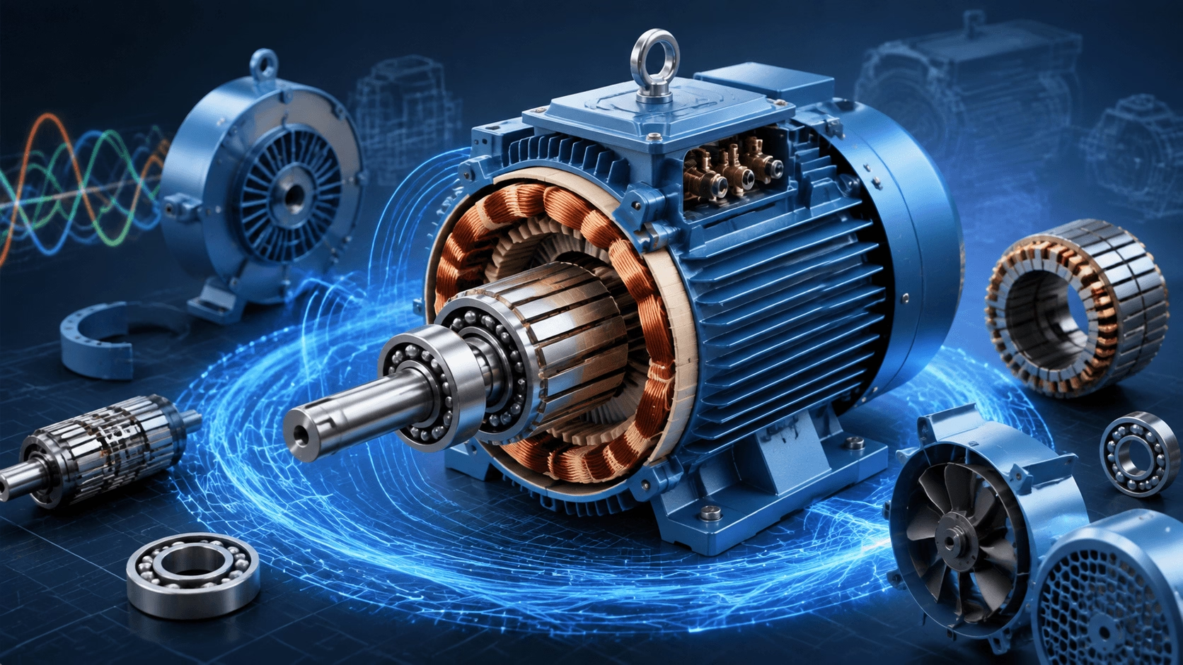
Understanding AC Motors: How Induction Motors Work | Technical Guide 2026
A comprehensive technical reference explaining AC motor operating principles, electromagnetic theory, construction details, performance characteristics, and efficiency standards. Essential knowledge for engineers, technicians, and procurement professionals involved in motor selection, application, and maintenance.
Introduction to AC Motor Technology
Principles, Construction & Operation for Industrial Applications
Alternating Current (AC) motors constitute the foundational electromechanical technology of modern industrial civilization, powering systems ranging from precision instrumentation to multi-megawatt heavy machinery. A rigorous understanding of their operating principles is essential for engineers, maintenance technicians, and technical buyers responsible for equipment specification, system integration, and lifecycle management.
This guide provides a structured technical exposition of AC motor fundamentals—covering electromagnetic theory, construction architecture, rotating field generation, slip mechanics, performance characteristics, and contemporary efficiency classifications—to support informed decision-making across industrial applications.
What Is an AC Motor?
An AC motor is an electromechanical transducer that converts alternating current electrical energy into continuous mechanical rotation. Unlike DC motors requiring mechanical commutation or electronic brushless controllers, AC induction motors operate through electromagnetic induction, a principle first described by Michael Faraday in 1831.
The enduring dominance of AC motors in industrial applications stems from three fundamental advantages:
- Simplicity: No brushes, commutators, or permanent magnets in standard induction designs
- Reliability: Minimal wearing components enable decades of continuous service
- Direct Grid Compatibility: Operate directly from standard AC power distribution without mandatory power electronics
Fundamental Electromagnetic Principles
AC motor operation rests on two interdependent physical laws:
1. Electromagnetic Induction (Faraday’s Law)
A time-varying magnetic field intersecting a conductor induces an electromotive force (EMF) proportional to the rate of flux change:
e = −N × dΦ/dt
Where e is induced EMF, N is number of turns, and dΦ/dt is rate of magnetic flux change. This principle enables contactless energy transfer from stator to rotor—the defining characteristic of induction machines.
2. Rotating Magnetic Field
The critical innovation enabling practical AC motors is the creation of a spatially rotating magnetic field within the stationary stator. When polyphase windings are energized with time-displaced currents, the resultant magnetic vector rotates at synchronous speed, dragging the rotor via electromagnetic coupling.
Construction Architecture of Induction Motors
The Stator (Stationary Assembly)
| Component | Function | Technical Specifications |
|---|---|---|
| Frame | Mechanical support, environmental protection, heat dissipation | Cast iron or aluminum alloy; IP54/IP55/IP65 ratings; foot/flange mounting per IEC 60034-7 |
| Core | Low-reluctance magnetic flux path; winding support | Laminated silicon steel (0.35–0.65 mm); inter-lamination insulation minimizes eddy current losses |
| Windings | Generate rotating magnetic field when energized | Insulated copper conductors; distributed in slots; star (Y) or delta (Δ) connection; three-phase sets displaced 120° electrical |
The Rotor (Rotating Assembly)
Squirrel Cage Rotor (Industry Standard)
- Construction: Laminated steel core with embedded conductive bars (aluminum die-cast or fabricated copper), short-circuited at both ends by end rings
- Electrical Interface: None—rotor currents are entirely induced via transformer action
- Characteristics: Simple, rugged, virtually maintenance-free; accounts for >90% of industrial AC motor installations
Wound Rotor (Slip Ring Motor)
- Construction: Three-phase insulated windings mirroring stator configuration; terminals connected to shaft-mounted slip rings
- External Circuit: Brushes permit connection to external resistors or power electronics
- Characteristics: Adjustable starting torque and speed control; higher complexity and maintenance; reserved for specialized high-inertia or variable-speed applications
Rotor Core & Shaft
- Laminated steel construction identical in principle to stator core
- Press-fit or keyed mounting on precision-ground steel shaft
- Bearing journals machined to ISO tolerance classes; dynamic balancing to ISO 1940 G2.5/G6.3
Rotating Magnetic Field Generation
Three-Phase Excitation
Balanced three-phase supply voltages are sinusoidally displaced by 120° electrical:
- Phase A: sin(ωt)
- Phase B: sin(ωt − 120°)
- Phase C: sin(ωt − 240°)
When these currents flow through spatially displaced stator windings, the superposition of individual phase fields produces a constant-magnitude magnetic vector rotating at synchronous speed.
Synchronous Speed Relationship
Ns = (120 × f) / P
Where:
- Ns = Synchronous speed (RPM)
- f = Supply frequency (Hz)
- P = Number of magnetic poles
| Poles | 50 Hz (RPM) | 60 Hz (RPM) |
|---|---|---|
| 2 | 3,000 | 3,600 |
| 4 | 1,500 | 1,800 |
| 6 | 1,000 | 1,200 |
| 8 | 750 | 900 |
Electromechanical Energy Conversion Sequence
The transformation from electrical input to mechanical output follows a precise causal chain:
- Field Rotation: Stator rotating magnetic field sweeps past rotor conductors at synchronous speed.
- EMF Induction: Relative motion between field and rotor induces voltage in rotor bars per Faraday’s Law.
- Current Flow: Induced EMF drives current through short-circuited rotor circuit.
- Force Generation: Rotor current interacting with stator field produces Lorentz force: F = I × B × L
- Torque Development: Circumferential forces integrate to produce net electromagnetic torque.
- Steady-State Operation: Rotor accelerates until developed torque equals load torque at equilibrium speed below synchronous speed.
Slip: The Essential Operating Parameter
Definition and Calculation
Slip is the normalized speed difference between synchronous field and actual rotor speed:
s = (Ns − N) / Ns × 100%
Where Ns is synchronous speed and N is actual rotor speed.
Typical Slip Values
| Operating Condition | Slip Range | Physical Significance |
|---|---|---|
| No Load | 0.1–0.5% | Minimal torque required; near-synchronous operation |
| Full Load | 2–6% | Rated torque production; design operating point |
| Starting (Locked Rotor) | 100% | Maximum induced EMF and current; peak torque development |
Why Slip Is Non-Negotiable
At zero slip (N = Ns), relative motion between field and rotor vanishes. Without relative motion, no EMF is induced, no rotor current flows, and no torque is produced. Slip is not a loss mechanism—it is the fundamental prerequisite for torque generation in induction machines.
Slip-Torque Relationship
Increased mechanical load demands greater torque → rotor decelerates → slip increases → induced EMF and rotor current increase → electromagnetic torque rises until equilibrium is restored. This self-regulating characteristic is inherent to induction motor physics.
AC Motor Classification
| Type | Key Characteristics | Primary Applications |
|---|---|---|
| Three-Phase Induction | Rugged, efficient, low maintenance, self-starting, constant speed | Pumps, fans, compressors, conveyors, machine tools, crushers |
| Single-Phase Induction | Capacitor-start/run variants for starting torque; lower power density | Residential HVAC, small pumps, fans, appliances, light commercial |
| Synchronous | Exact synchronous speed; unity or leading power factor capability | Precision speed processes, large compressors, power factor correction, generators |
| Wound Rotor Induction | External rotor resistance control; adjustable starting torque/speed | High-inertia starts, cranes, hoists, wound-rotor VFD alternatives |
Performance Characteristics
Torque-Speed Curve Anatomy
| Torque Point | Typical Value (% Full Load) | Engineering Significance |
|---|---|---|
| Starting (Locked Rotor) | 150–250% | Breakaway capability; must exceed static friction and load inertia |
| Pull-Up | 100–200% | Minimum torque during acceleration; must exceed load torque throughout run-up |
| Breakdown (Maximum) | 200–300% | Stability limit; operation beyond this point causes stall |
| Full Load | 100% (rated) | Continuous duty operating point; thermal design basis |
Efficiency Fundamentals
η = (P_out / P_in) × 100%
Loss categories reducing efficiency:
- Stator Copper Losses (I²R): Conductor resistance heating
- Rotor Copper Losses (I²R): Slip-dependent; proportional to slip × air-gap power
- Core (Iron) Losses: Hysteresis + eddy currents in laminations
- Friction & Windage: Bearing drag + cooling fan aerodynamic losses
- Stray Load Losses: Harmonic effects, leakage flux, manufacturing imperfections
IE Efficiency Classes (IEC 60034-30-1)
| Class | Designation | Full-Load Efficiency Range | 2026 Regulatory Status |
|---|---|---|---|
| IE1 | Standard | ~82–85% | Obsolete in regulated markets |
| IE2 | High | ~87–90% | Minimum in select emerging economies |
| IE3 | Premium | 90–95% | Mandatory baseline in EU, US, China, India, Australia |
| IE4 | Super Premium | 95–97%+ | Mandatory 75–200 kW in EU; expanding globally |
Design Note: Achieving IE4+ requires premium silicon steel, optimized slot/pole combinations, tighter air gaps, and precision manufacturing. Efficiency gains compound significantly over 15–20 year service lives in continuous-duty applications.
Motor Selection Framework
| Category | Parameters | Considerations |
|---|---|---|
| Electrical | Voltage, frequency, phase, starting current, efficiency class | Grid compatibility; VFD suitability; MEPS compliance |
| Mechanical | Power rating, speed, torque profile, mounting, frame size | Load matching; overload margin; dimensional interchangeability |
| Environmental | Ambient temperature, altitude, humidity, contaminants, hazardous areas | IP rating; insulation class; cooling method; explosion protection |
| Operational | Duty cycle (S1–S10), service factor, expected life, maintenance access | Thermal capacity; bearing L10 life; seal specification; spare parts availability |
Conclusion: Enduring Engineering Excellence
The AC induction motor represents one of the most elegant and consequential technologies in engineering history. Its operation—grounded entirely in Faraday’s law of electromagnetic induction and the rotating magnetic field—requires no sliding electrical contacts, permanent magnets, or complex control electronics for basic functionality. This inherent simplicity, combined with continuous refinement in materials science and manufacturing precision, has sustained its dominance as the industrial workhorse for over a century.
At Titecho, these fundamental principles inform every design decision, material selection, and quality verification step. Our commitment to electromagnetic optimization, premium construction, and rigorous testing ensures that each motor we manufacture delivers reliable, efficient performance throughout its full service life—honoring the physics that made the AC motor possible while advancing it for the demands of 2026 and beyond.
Expert Support from Titecho
For technical consultation on AC motor selection, application engineering, or custom specifications:
🌐 Technical Resources & Product Portfolio: www.cntecho.com
✉️ Engineering Inquiries & Quotations: [email protected]
Titecho: Where fundamental physics meets precision manufacturing.