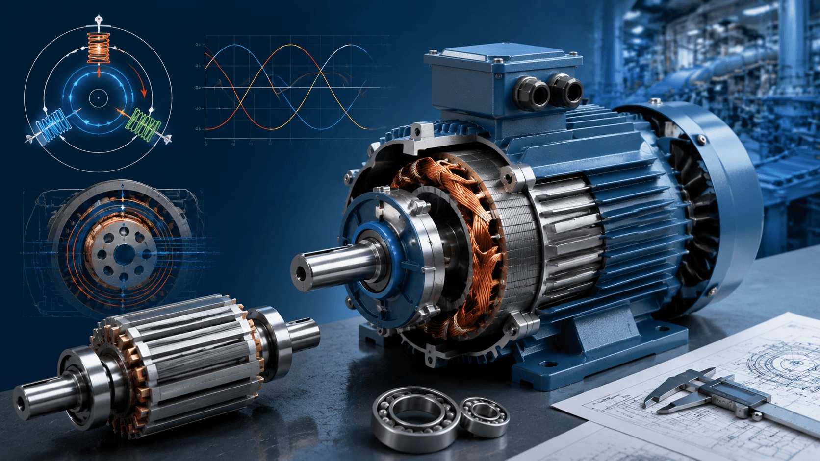
A foundational technical guide detailing the operational principles, core components, and electromagnetic mechanics of three-phase induction motors—the most ubiquitous prime movers in modern industrial applications. Expert insights from Techo Electrical & Mechanical (Titecho).
1. Introduction
Three-phase induction motors represent the cornerstone of industrial drive systems, converting three-phase alternating current (AC) into mechanical torque utilising a rotating magnetic field. Characterised by their self-starting capability, rugged construction, and minimal maintenance requirements, they are the dominant choice for driving pumps, fans, compressors, and conveyors globally.
This guide elucidates the fundamental electromagnetic principles, structural components, and torque production mechanisms that govern the operation of these critical assets.
2. Core Components and Construction
An induction motor operates without brushes or a direct electrical connection to the rotor, relying entirely on electromagnetic induction. The primary structural elements include:
| Component | Description and Function |
|---|---|
| Stator (Stationary) | Comprises a laminated silicon steel core to minimise eddy current losses. It houses three sets of spatially distributed windings, displaced by 120 electrical degrees. When energised by a three-phase AC supply, these windings generate the Rotating Magnetic Field (RMF). |
| Rotor (Rotating) | Squirrel-Cage: Consists of conductive bars (aluminium or copper) short-circuited by end rings. Highly robust and low-maintenance. Wound-Rotor: Features insulated windings connected to external slip rings, allowing the insertion of external resistance to optimise starting torque. |
| Air Gap | The critical, minimal radial clearance between the stator and rotor. A precise, uniform air gap is essential for magnetic efficiency and preventing mechanical rubbing. |
| Mechanical Assembly | Includes the machined output shaft, precision bearings (to support radial and axial loads), and robust end shields (bearing housings) that maintain structural alignment. |
3. The Rotating Magnetic Field (RMF)
The fundamental operating principle of the induction motor is the creation of a Rotating Magnetic Field (RMF).
When balanced, three-phase sinusoidal currents of equal amplitude flow through the stator windings, each phase produces its own pulsating magnetic flux. The vector sum of these three spatially and temporally displaced fluxes results in a single, constant-magnitude magnetic flux vector that rotates steadily around the stator periphery.
Synchronous Speed
The rotational velocity of this magnetic field, known as the synchronous speed, is dictated strictly by the supply frequency and the physical pole configuration of the stator:
ns = (120 × f) / P
Where:
- ns = Synchronous speed (Revolutions Per Minute, RPM)
- f = Supply frequency (Hertz, Hz)
- P = Total number of magnetic poles (always an even integer)
The Necessity of Slip
For torque to be produced, the physical rotor must rotate at a speed slightly lower than the synchronous speed of the RMF. This velocity differential is termed slip. If the rotor were to reach synchronous speed, the relative motion between the RMF and the rotor conductors would cease, halting electromagnetic induction and resulting in zero torque production.
4. Electromagnetic Torque Production: A Step-by-Step Process
The conversion of electrical energy to mechanical work follows a precise electromagnetic sequence:
- Flux Interception: The stator's RMF sweeps past the stationary (or slower-moving) rotor conductors.
- Electromagnetic Induction (Faraday’s Law): The time-varying magnetic flux linking the rotor bars induces an Electromotive Force (EMF). Because the rotor bars are short-circuited by the end rings, this EMF drives substantial induced currents through the rotor.
- Force Generation (Lorentz Force / Lenz’s Law): The induced rotor currents generate their own secondary magnetic field. The interaction between this rotor magnetic field and the primary stator RMF produces a tangential electromagnetic force, manifesting as rotational torque.
- Kinematic Equilibrium: The rotor accelerates until the generated electromagnetic torque precisely balances the mechanical load torque and internal friction, stabilising at an operating speed slightly below synchronous speed.
5. Starting Methods and Speed Control
5.1 Starting Characteristics
- Squirrel-Cage Motors: Inherently self-starting when connected directly to a three-phase supply (Direct-On-Line). However, they draw high inrush currents (typically 6 to 8 times the full-load current) and produce moderate starting torque.
- Wound-Rotor Motors: Allow the insertion of external resistors via slip rings during startup. This reduces inrush current while simultaneously maximising starting torque, making them ideal for high-inertia loads like large crushers or mills.
5.2 Speed Control via VFDs
Historically, induction motors were considered fixed-speed devices. Today, the integration of Variable Frequency Drives (VFDs) allows precise control of both speed and torque by dynamically adjusting the supply frequency and voltage. This not only enables complex process control but also yields massive energy savings in variable-torque applications.
6. Maintenance, Fault Diagnosis, and Selection
6.1 Common Operational Faults
Despite their ruggedness, induction motors are susceptible to specific failure modes if improperly applied or maintained:
| Fault Category | Primary Causes |
|---|---|
| Bearing Failure | Inadequate lubrication, misalignment, excessive belt tension, or electrical discharge machining (EDM) currents from VFDs. |
| Insulation Breakdown | Thermal degradation from chronic overloading, voltage spikes, or moisture/chemical ingress. |
| Overheating | Poor ventilation, high ambient temperatures, voltage imbalance, or operation at excessive slip. |
| Vibration & Imbalance | Rotor unbalance, soft foot, resonance, or broken rotor bars. |
6.2 Strategic Selection Guidelines
- General Applications: Specify squirrel-cage rotors for their mechanical simplicity, high efficiency, and minimal lifecycle maintenance.
- High-Inertia / High-Torque Starts: Specify wound-rotor designs or utilise soft-starters/VFDs to manage mechanical and electrical stress.
- Energy-Sensitive Systems: Mandate premium efficiency classes (IE3 or IE4) and integrate VFDs to optimise part-load energy consumption and reduce Total Cost of Ownership (TCO).
7. Conclusion
The three-phase induction motor remains an unparalleled achievement in electromechanical engineering, offering a robust, efficient, and highly reliable solution for industrial power transmission. Understanding the interplay between the rotating magnetic field, slip, and torque production is essential for system integrators and plant engineers to specify, operate, and maintain these assets effectively.
Techo Electrical & Mechanical (Titecho) supplies a comprehensive portfolio of high-efficiency three-phase induction motors, engineered for optimal performance across diverse industrial applications. Our technical team provides expert guidance on motor selection, VFD integration, and lifecycle reliability strategies.
Explore our technical specifications, efficiency curves, and engineering support at www.cntecho.com.
© Techo Electrical & Mechanical (Titecho) – Advancing Industrial Electromechanical Excellence