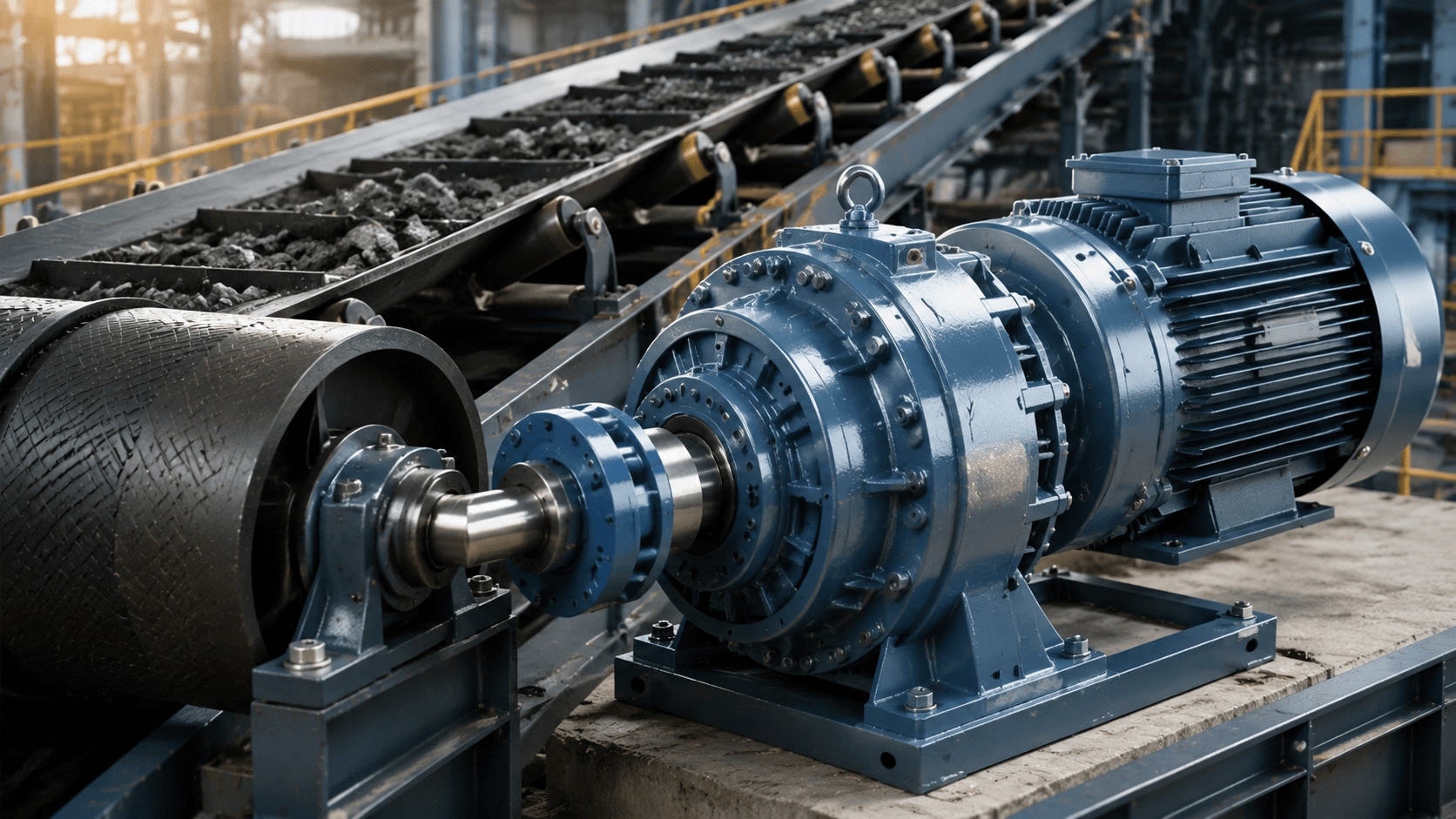
A comprehensive 2026 engineering guide to cycloidal reducers for belt conveyor applications, encompassing working principles, mechanical benefits, systematic sizing procedures, installation best practices, comparative analysis, and reliability optimisation strategies.
1. Introduction
Belt conveyors constitute the backbone of modern material handling infrastructure across diverse sectors, including mining and aggregates, food processing, logistics, manufacturing, and packaging. These systems transport bulk materials or packaged goods over extensive distances, frequently operating under variable loads, inclined trajectories, frequent start-stop cycles, and sudden impact loads from material surges. Consequently, the selection of an appropriate speed reducer is critical for ensuring reliable operation, maximising energy efficiency, minimising unplanned downtime, and extending equipment service life.
Cycloidal reducers (also designated as cycloidal gearboxes, cyclo drives, or cycloidal speed reducers) distinguish themselves in numerous belt conveyor applications due to their unique mechanical architecture. They offer exceptional torque density within a compact envelope, superior shock load resistance, near-zero backlash, high torsional stiffness, and extended durability under demanding operational conditions. Unlike traditional worm or helical gearboxes, cycloidal units distribute mechanical loads across multiple contact points through rolling motion, rendering them particularly resilient to the irregular and dynamic loads prevalent in conveyor systems.
This practical guide examines the working principles of cycloidal reducers, their specific engineering benefits for belt conveyors, a systematic step-by-step selection process, installation and mounting considerations, comparative analysis against alternative technologies, maintenance best practices, real-world application examples, and critical edge cases. Whether you are a system integrator, plant engineer, or Original Equipment Manufacturer (OEM) designing or upgrading a conveyor line, this guide provides actionable technical insights for optimal integration.
2. Understanding Cycloidal Reducers: Design and Operating Principles
A cycloidal reducer converts high-speed, low-torque motor input into low-speed, high-torque output through a distinctive and highly efficient kinematic mechanism:
- Eccentric Drive: An input shaft equipped with an eccentric cam or bearing drives one or more cycloidal discs.
- Rolling Reduction: The cycloidal disc orbits within a stationary ring of pins; its lobes mesh with the fixed pins, generating a high-reduction rolling motion without sliding friction.
- Output Transmission: Output pins or rollers engage with the cycloidal disc to transmit the reduced rotary motion to the output shaft.
Key Mechanical Characteristics
| Parameter | Engineering Specification |
|---|---|
| Reduction Ratios | Single-stage ratios typically range from 10:1 to 87:1; multi-stage configurations can achieve ratios in the thousands. |
| Load Distribution | Load is distributed across 30–50% of the cycloidal lobes simultaneously, providing superior torque capacity and shock absorption. |
| Efficiency | Rolling contact mechanics yield high mechanical efficiency, typically 90–97% for single-stage units, reducing wear and vibration. |
| Stiffness & Backlash | High torsional rigidity and minimal backlash ensure smooth, precise belt speed control. |
Modern cycloidal reducers incorporate hardened alloy steel components, precision-ground profiles, advanced grease or oil lubrication systems, hollow-shaft options, and integrated motor mounting flanges—features ideally suited for conveyor drives where spatial constraints and reliability are paramount.
3. Why Cycloidal Reducers Excel in Belt Conveyor Applications
Belt conveyors frequently encounter demanding operational challenges:
- Heavy or uneven loads causing sudden torque spikes.
- Emergency stops, material jams, or surge loading.
- Continuous or high-duty-cycle operation.
- The requirement for smooth, consistent belt speed.
- Spatial constraints near drive pulleys.
Cycloidal reducers address these challenges effectively through the following advantages:
| Advantage | Operational Benefit for Conveyors |
|---|---|
| Superior Shock Load Capacity | Distributed contact points absorb sudden impacts from material surges or jams far more effectively than conventional gear teeth. |
| High Torque at Low Speeds | Delivers robust torque output for driving heavily loaded conveyors at low operational speeds. |
| Compact Size & High Torque Density | Facilitates installation in space-constrained drive areas near pulleys or within conveyor frames. |
| Low Backlash & High Stiffness | Ensures precise belt positioning and prevents positional drift during start-stop cycles. |
| Long Service Life & Low Maintenance | Rolling friction mechanics drastically reduce component wear, minimising maintenance intervals. |
| Smooth, Low-Vibration Performance | Reduces structural vibration and acoustic noise, protecting belt integrity and supporting structure. |
Note: Limitations may include larger radial dimensions in certain high-ratio designs and the necessity for careful thermal management in high-duty-cycle environments.
4. Step-by-Step Selection Process for Belt Conveyor Applications
Systematic sizing is essential to ensure optimal performance and longevity. Follow this structured methodology:
Step 1: Define Conveyor Parameters and Load Profile
Gather comprehensive application data, including:
- Conveyor length, belt width, and belt speed.
- Material density and maximum load capacity.
- Incline angle and duty cycle (operating hours per day).
- Environmental conditions (temperature, dust, humidity).
Calculate the effective pull (tension) using standard conveyor engineering formulas.
Step 2: Calculate Required Torque and Power
Determine the mechanical requirements using the following text-based formulas:
Output Torque = (Effective Tension × Pulley Radius) × Service Factor
Motor Power = (Output Torque × Output Speed) / (9550 × Efficiency)
(Note: Torque in N·m, Speed in rpm, Power in kW)
Step 3: Determine Reduction Ratio
Calculate the required speed reduction:
Reduction Ratio = Motor RPM / Drum RPM
Cycloidal units excel at providing high reduction ratios in a single stage, simplifying the drivetrain architecture.
Step 4: Select Model and Size
Match the calculated output torque (including the applied service factor) against manufacturer catalogue ratings. Consider the following integration parameters:
- Mounting configuration (foot-mounted, shaft-mounted, flange-mounted).
- Motor type and compatibility (IEC/NEMA frame sizes).
- Solid or hollow shaft requirements.
- Catalogue thermal ratings.
Step 5: Evaluate Environmental and Integration Factors
Verify the following operational constraints:
- Ingress Protection (IP) Rating: Ensure adequate sealing for dusty or wet environments.
- Lubrication: Select appropriate grease or oil based on ambient temperature and duty cycle.
- Overhung Load Capacity: Verify that output bearings can withstand belt tension forces.
- Thermal Limits: Ensure the gearbox can dissipate heat generated during continuous operation.
- Backlash Requirements: Confirm precision needs for belt tracking and positioning.
Engineering Tip: Oversize the reducer by approximately 20–30% to enhance longevity and accommodate unexpected load spikes, but avoid excessive oversizing which can reduce efficiency and increase cost.
5. Mounting, Installation, and Integration Best Practices
Proper installation is critical to maximise the service life and performance of cycloidal reducers in conveyor applications.
5.1 Common Mounting Configurations
- Horizontal Foot-Mounted: Standard configuration for most conveyor drive stations.
- Shaft-Mounted with Torque Arm: Frequently used where the reducer mounts directly onto the drive pulley shaft.
5.2 Installation Guidelines
- Precise Alignment: Ensure exact alignment between the motor, reducer, and driven pulley to prevent premature bearing wear and vibration.
- Torque Arm Installation: For shaft-mounted units, a properly installed torque arm is essential to react output torque and prevent housing rotation.
- Lubrication Compliance: Strictly follow manufacturer guidelines for lubricant type, fill quantity, and initial break-in procedures.
- Soft Start Integration: Utilise Variable Frequency Drives (VFDs) to provide controlled acceleration, reducing mechanical shock during startup and enabling adjustable belt speed.
6. Comparison with Alternative Reducers for Belt Conveyors
| Gear Technology | Comparative Analysis vs. Cycloidal Reducers |
|---|---|
| Worm Gearboxes | Cycloidal drives offer significantly higher mechanical efficiency, superior shock load handling, and longer service life. Worm drives are typically limited to lower torque capacities and generate more heat. |
| Helical / Bevel Gearboxes | Helical units provide slightly higher efficiency but are generally larger and less resistant to shock loads. Cycloidal drives offer superior compactness and impact resilience. |
| Planetary Reducers | Planetary gearboxes excel in high-precision applications but can be susceptible to tooth damage under severe shock loading. Cycloidal drives provide unmatched durability under variable and high-impact conveyor loads. |
7. Maintenance, Monitoring, and Lifecycle Considerations
Although cycloidal reducers require minimal maintenance compared to alternative technologies, a structured preventive maintenance programme is recommended:
- Regular Visual Inspections: Check for oil leaks, unusual noise, or excessive vibration.
- Lubricant Management: Monitor lubricant condition and adhere to recommended replacement intervals.
- Condition Monitoring: Track operating temperature and vibration signatures to detect early signs of wear or misalignment.
- Spare Parts Strategy: Maintain critical spare parts inventory to minimise downtime during unexpected failures.
Lifecycle Cost Benefit: The total cost of ownership for cycloidal reducers is highly favourable due to reduced maintenance frequency, lower energy consumption, and extended service intervals.
Case Example: A major distribution centre reported a 62% reduction in conveyor maintenance costs after transitioning from traditional gearboxes to cycloidal drives, attributed to superior shock absorption and reduced wear.
8. Real-World Applications and Edge Cases
8.1 Industry-Specific Applications
- Mining & Aggregates: Exceptional shock resistance handles heavy rock and aggregate surges.
- Food & Beverage: Hygienic, sealed versions comply with washdown requirements and prevent contamination.
- Logistics & Warehousing: Compact layouts and frequent stop-start capabilities suit automated sorting systems.
- Packaging: Smooth, low-vibration speed control ensures precise product handling.
8.2 Engineering Edge Cases
- Long or Steep Conveyors: Require higher service factors and robust braking systems to manage gravitational loads.
- Extreme Temperature Environments: Necessitate specialised synthetic lubricants and thermal derating.
- High-Speed Duty Cycles: Require verification of thermal ratings and potential forced cooling.
- Retrofit Projects: Cycloidal reducers often improve performance and reliability when replacing aging worm or helical units.
9. Conclusion: Optimising Belt Conveyor Performance
Cycloidal reducers deliver a robust, efficient, and durable power transmission solution for belt conveyor drives, particularly in applications characterised by shock loads, variable operating conditions, or stringent reliability requirements. By following a systematic selection process and carefully considering environmental and integration factors, engineers can achieve smooth operation, significantly reduced maintenance burdens, and lower total ownership costs.
When integrated with modern electric motors, Variable Frequency Drives (VFDs), and condition monitoring systems, cycloidal technology substantially enhances conveyor uptime and overall productivity. Early consultation with experienced manufacturers ensures optimal component selection, customisation, and long-term operational value.
10. Engineered Conveyor Drive Solutions with Titecho
Techo Electrical & Mechanical (Taizhou) Co., Ltd. (Brand: Titecho) specialises in high-performance cycloidal reducers and integrated conveyor drive systems engineered for demanding material handling applications. Our product portfolio features precision-ground cycloidal profiles, heavy-duty bearing arrangements, advanced sealing technologies, and flexible mounting configurations tailored for belt conveyor reliability.
We provide comprehensive engineering support, including torque calculations, thermal modelling, 3D CAD integration, and custom motor adaptations to meet your specific project requirements.
Explore technical data sheets, performance curves, and application engineering support at www.cntecho.com.
© Techo Electrical & Mechanical (Titecho) – Precision Power Transmission for Reliable Material Handling