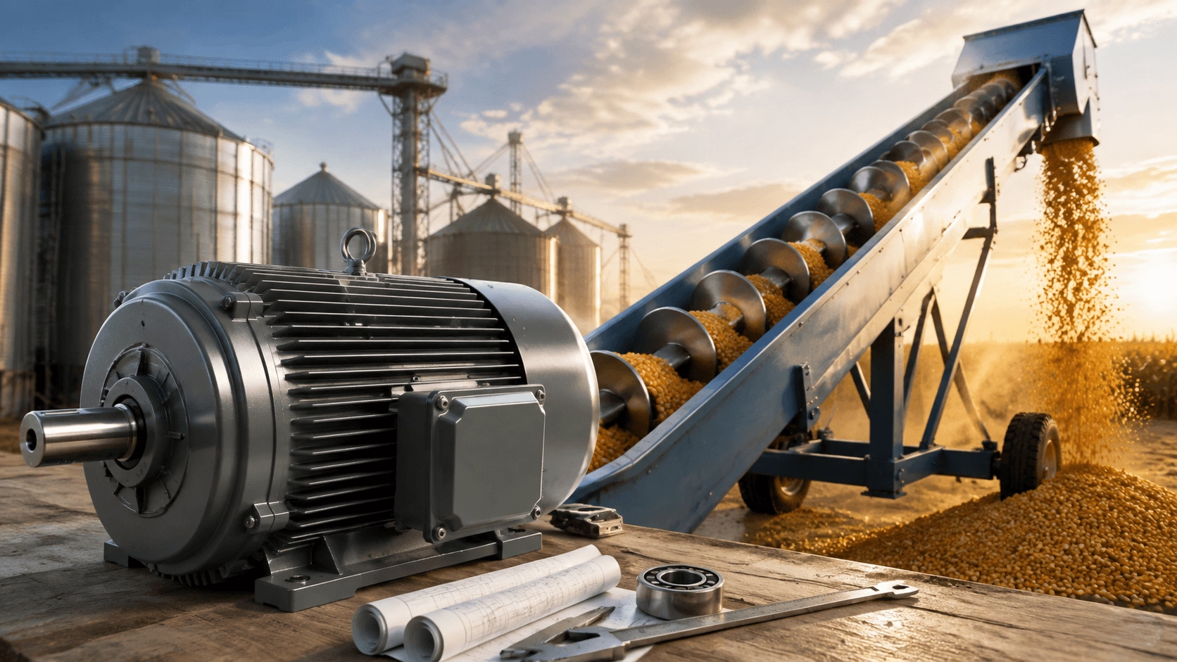
A comprehensive 2026 engineering guide to customising AC motors for grain augers, encompassing torque sizing, enclosure protection, hazardous location ratings, mechanical mounting, factory testing, and system integration protocols.
1. Introduction
Grain augers (screw conveyors) are indispensable components in agricultural operations, grain handling terminals, feed mills, and bulk material processing facilities. These systems efficiently transport dry or moist grain, seed, and feed across horizontal, inclined, or vertical trajectories. The drive motor must deliver exceptional starting torque to overcome initial static friction and material head load, operate reliably in dusty, outdoor, and variable-load environments, and integrate seamlessly with gearboxes, pulleys, or direct-drive assemblies while minimising downtime and energy consumption.
Standard off-the-shelf motors frequently fail to meet the rigorous demands of these operating conditions. Custom AC induction motors (typically three-phase or single-phase farm-duty designs) enable precise tailoring of power ratings, torque characteristics, enclosure protection, mounting configurations, thermal management, and electrical parameters. Customisation ensures the motor aligns perfectly with the auger’s length, diameter, incline angle, material characteristics, duty cycle, and critical safety requirements—such as dust ignition protection in combustible grain environments.
This practical, step-by-step guide provides system integrators, Original Equipment Manufacturers (OEMs), agricultural engineers, and facility operators with a structured methodology for the customisation process. It covers data acquisition, performance calculations, specification development, supplier collaboration, validation testing, and installation considerations. Examples reference typical 6–12 inch diameter augers handling corn, wheat, or soybeans at capacities ranging from a few tons to several hundred tons per hour.
2. Step 1: Gather Comprehensive Application Data
Successful customisation begins with a rigorous definition of application requirements. Collect and document the following parameters:
2.1 Mechanical and Process Specifications
- Auger Geometry: Diameter, total length, incline angle, flight pitch, screw design, and nominal operating speed.
- Material Characteristics: Grain type, bulk density, moisture content, flowability index, and abrasiveness.
- Capacity and Duty Cycle: Required throughput (tons/hour), continuous versus intermittent operation, frequency of starts/stops, and seasonal operating hours.
2.2 Environmental and Electrical Parameters
- Environmental Conditions: Ambient temperature ranges, dust concentration levels (combustible dust classification), moisture exposure, and outdoor weathering factors.
- Power Supply: Available voltage, frequency, phase configuration, and short-circuit current availability.
- Mechanical Interface: Gearbox reduction ratio, pulley configurations, coupling types, shaft dimensions, and mounting orientation.
2.3 Safety and Compliance Requirements
- Regulatory Codes: Compliance with National Electrical Code (NEC) or local equivalents.
- Protection Requirements: Overload protection settings, explosion-proof or dust-ignition-proof ratings, and Variable Frequency Drive (VFD) compatibility.
Engineering Note: Document all parameters in a detailed specification sheet or Request for Quotation (RFQ) template. Include worst-case operational scenarios, such as starting under full load or upset conditions.
3. Step 2: Calculate Power, Torque, and Performance Requirements
Utilise established engineering methodologies (e.g., Conveyor Equipment Manufacturers Association (CEMA) guidelines) to size the motor conservatively:
3.1 Conveyor Horsepower Calculation
Determine the total mechanical power required at the drive shaft:
Total Shaft HP = (Friction HP + Material HP) × Incline Factor / Drive Efficiency
3.2 Starting Torque Verification
Augers frequently require substantial torque to initiate rotation against static material loads:
- Starting Torque Requirement: Augers typically demand 2.0 to 2.5 times the running torque at startup.
- Locked Rotor Torque (LRT) Target: Specify 200% to 300% of full-load torque.
- Pull-Up and Breakdown Torque: Ensure these values exceed the maximum anticipated load spikes during acceleration.
3.3 Speed, Ratio, and Service Factor
- Base Speed: Most AC induction motors operate at approximately 1750 RPM. Pair the motor with a gearbox or pulley system to achieve the optimal auger RPM.
- Service Factor: Apply a service factor of 1.15 to 1.5 (or higher) to accommodate shock loads and material surges.
3.4 Efficiency and Thermal Design
- Specify premium efficiency classes (IE3/IE4 or NEMA Premium®).
- Utilise Totally Enclosed Fan Cooled (TEFC) enclosures to prevent dust ingress and manage thermal dissipation.
4. Step 3: Define Custom Motor Features and Enclosure
Translate calculated requirements into specific motor design features:
| Feature Category | Customisation Options |
|---|---|
| Enclosure & Protection | TEFC/TENV designs, dust-ignition-proof certification, IP55 or higher ingress protection, sealed bearings. |
| Thermal Protection | Embedded overload protectors, thermostats, thermistors (PTC), and overspeed guards. |
| Torque & Electrical Design | High starting torque windings, capacitor-start/capacitor-run configurations, robust rotor bar design. |
| Mounting & Mechanical | Custom flanges, foot mounts, special shaft dimensions, reinforced bearing arrangements. |
| Insulation & Materials | Class F or Class H insulation systems, tropicalisation treatment, cast iron or heavy-gauge aluminium frames. |
| Additional Options | Space heaters for condensation prevention, drain plugs, VFD-rated insulation and bearing protection. |
Strategic Note: Balance customisation with cost-effectiveness. Minor modifications to standard platforms are economical; major redesigns significantly increase lead time and non-recurring engineering (NRE) costs.
5. Step 4: Collaborate with Manufacturer and Issue RFQ
Select suppliers with proven expertise in agricultural and bulk material handling motors.
RFQ Submission Checklist
- Submit the detailed RFQ containing all application data gathered in Step 1.
- Request performance curves (torque-speed, efficiency, current), thermal data, dimensional drawings, and 3D CAD models.
- Discuss value engineering opportunities and integration options to reduce total system cost.
- Review certification documentation (UL, CE, ATEX/IECEx if applicable) and warranty terms.
Note: Lead times for custom motors typically range from 4 to 12 weeks, depending on complexity and testing requirements.
6. Step 5: Prototype, Test, and Validate
Rigorous validation ensures the custom motor performs reliably under real-world conditions.
6.1 Factory Acceptance Testing (FAT)
- No-Load Test: Verify bearing operation, noise levels, and vibration signatures.
- Locked-Rotor Test: Confirm starting torque and locked rotor current.
- Full-Load Performance Test: Validate efficiency, temperature rise, and current draw under rated conditions.
- Vibration Analysis: Ensure compliance with ISO 10816 standards.
6.2 Field Testing and Validation
- Run the motor under loaded, inclined, and startup conditions simulating actual auger operation.
- Edge Case Testing: Evaluate performance with wet grain, full-load restarts, and voltage fluctuations.
- Iterate the design if performance deviates from specifications.
- Document all test data for compliance records and future reference.
7. Step 6: Installation, Integration, and Maintenance Planning
Proper installation and maintenance protocols are critical for long-term reliability.
7.1 Installation Best Practices
- Ensure precise mounting and shaft alignment to prevent premature bearing failure.
- Configure electrical systems with correctly sized overload protection and grounding.
- Verify proper belt tensioning and gearbox lubrication.
- Safety Compliance: Install physical guards, emergency stop systems, and ensure equipotential bonding.
7.2 Maintenance Strategy
- Establish regular lubrication schedules for bearings and gearboxes.
- Perform periodic insulation resistance testing and thermal protector verification.
- Train operators on overload response, manual-reset procedures, and abnormal noise identification.
8. Comparison: Standard vs. Custom Motors and Alternatives
Standard farm-duty motors are suitable for simple, light-duty setups but may lack optimised torque curves, enhanced dust protection, or exact mounting configurations. Custom motors are essential when:
- Higher horsepower or extreme starting torque is required.
- Hazardous location ratings (combustible dust) apply.
- Unique flanges, shafts, or space constraints exist.
Alternative Technologies
- Hydraulic Drives: Offer variable speed but require hydraulic power units and are prone to leaks and lower overall efficiency.
- DC Motors: Provide high starting torque but require brush maintenance and are less suited for harsh, dusty environments.
- AC Induction Motors: Offer superior reliability, lower maintenance, and higher efficiency compared to alternatives.
Engineering Nuances and Edge Cases
- High-Moisture Grain: Requires a higher service factor to prevent stalling.
- Very Long Augers: May necessitate multiple drive points to reduce shaft torsional stress.
- Cold Climates: Specify space heaters to prevent condensation freezing.
- VFD Operation: Mandate inverter-duty insulation and shaft grounding protection.
9. Conclusion: Achieving Reliable, Optimised Performance
Customising an AC motor for a grain auger transforms a potential operational weak link into a robust, application-specific powerhouse. By systematically gathering data, performing accurate calculations, specifying tailored features, collaborating closely with manufacturers, and validating through rigorous testing, engineers ensure high starting torque, dust and thermal resilience, seamless integration, and extended service life.
This structured approach minimises unplanned downtime, reduces energy consumption, and ensures compliance with critical safety standards in combustible grain environments. For optimal results, engage motor specialists early in the design phase and share detailed mechanical drawings for deep optimisation.
10. Engineered Agricultural Drive Solutions with Titecho
Techo Electrical & Mechanical (Taizhou) Co., Ltd. (Brand: Titecho) specialises in high-performance custom AC motors engineered for demanding agricultural and bulk material handling applications. Our product portfolio features high-torque rotor designs, dust-ignition-proof enclosures, advanced sealing technologies, and flexible mounting configurations tailored for grain auger reliability.
We provide comprehensive engineering support, including torque calculations, thermal modelling, 3D CAD integration, and custom motor adaptations to meet your specific project requirements.
Explore technical data sheets, performance curves, and application engineering support at www.cntecho.com.
© Techo Electrical & Mechanical (Titecho) – Precision Power Transmission for Agricultural Excellence