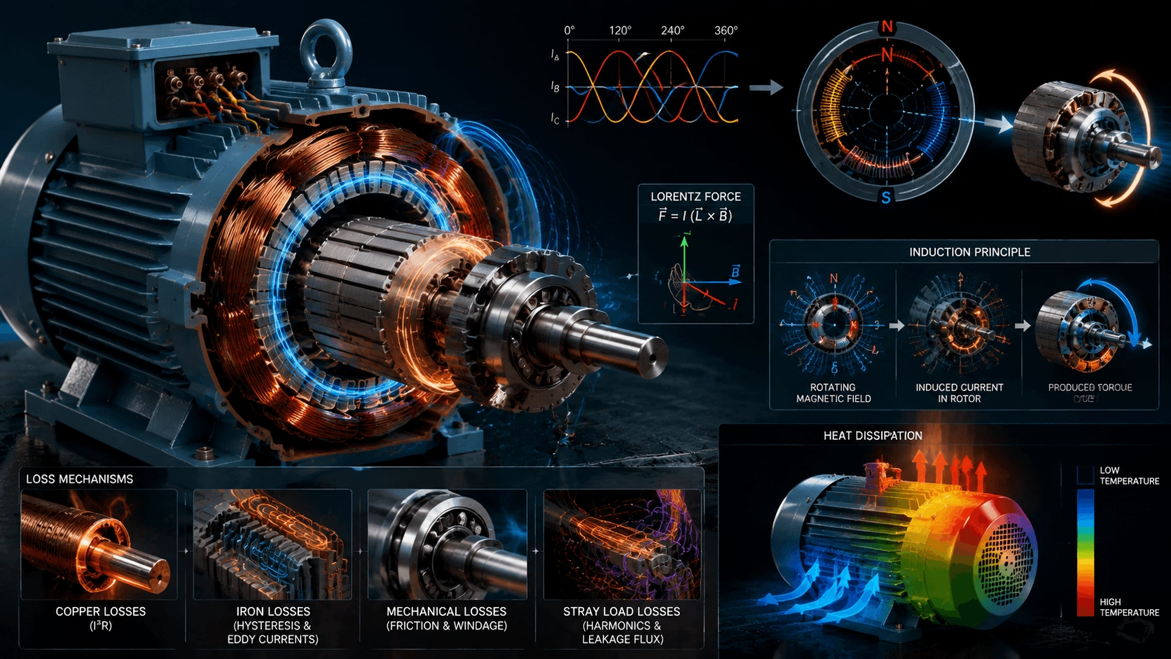
How Electric Motors Work: A Deep Dive into Electromagnetism and Motion
Abstract: A comprehensive scientific explanation of the principles governing electric motor operation. This article explores electromagnetism, rotating magnetic fields, rotor dynamics, energy conversion losses, and thermal management, providing a foundational understanding of how electrical energy is transformed into mechanical motion.
1. Introduction: The Ubiquity of Electric Motion
Electric motors represent one of the most consequential inventions of the modern industrial era. They power systems ranging from domestic appliances to large-scale industrial pumps and electric vehicles. Despite their ubiquity, the underlying physics enabling stationary metal assemblies to generate substantial rotational force remains poorly understood outside specialized engineering disciplines.
This article provides a rigorous yet accessible examination of the scientific principles governing electric motors, focusing on the fundamental mechanisms of electrical-to-mechanical energy conversion.
2. The Foundation: Electromagnetism
The operation of every electric motor is grounded in electromagnetism—the physical relationship between electric current and magnetic fields.
- Current-Induced Magnetic Fields: When electric current flows through a conductor (e.g., copper winding), it generates a concentric magnetic field around that conductor. The field strength is directly proportional to current magnitude.
- Lorentz Force: When this generated magnetic field interacts with an external magnetic field (from permanent magnets or other electromagnets), a mechanical force is produced. This electromagnetic force, known as the Lorentz Force, is the fundamental mechanism that converts electrical energy into mechanical torque.
3. The Rotating Magnetic Field (RMF)
In Alternating Current (AC) motors, continuous rotation depends on the creation of a Rotating Magnetic Field.
3.1 Alternating Current Characteristics
Unlike Direct Current (DC), which flows unidirectionally, AC reverses direction periodically at a defined frequency (typically 50 Hz or 60 Hz). This oscillation is essential for generating a time-varying magnetic field.
3.2 Phase Shift and Spatial Arrangement
In three-phase motors, three separate currents are temporally offset by 120 electrical degrees. When these phase-shifted currents flow through stator windings arranged symmetrically around the motor circumference, they produce a resultant magnetic field vector that rotates continuously at synchronous speed.
3.3 Rotor Interaction
This rotating magnetic field sweeps past the rotor conductors or magnets, inducing current (in induction motors) or exerting direct magnetic attraction (in synchronous motors). The rotor continuously attempts to align with the rotating field, producing sustained mechanical rotation.
Conceptual Analogy: Imagine multiple people standing in a circle, each holding a magnet. If they sequentially reorient their magnets in coordinated timing, a magnetic pole appears to travel around the circle. A ferromagnetic object placed at the center would attempt to follow this moving pole—this is the essential principle of RMF-driven rotation.
4. Types of AC Motors
While all AC motors rely on electromagnetic interaction, construction and operating principles vary significantly:
| Motor Type | Operating Mechanism | Key Characteristics |
|---|---|---|
| Induction Motor | Rotor current induced by stator magnetic field via electromagnetic induction | Robust construction, brushless, inherent slip, widely used in industry |
| Synchronous Motor | Rotor locks precisely to rotating magnetic field speed | Zero slip, precise speed control, higher efficiency, requires excitation or PM rotor |
| Brushless DC (BLDC) | Electronic commutation replaces mechanical brushes | High controllability, high power density, used in precision and variable-speed applications |
5. Energy Conversion and Loss Mechanisms
No electromechanical conversion achieves 100% efficiency. Understanding loss mechanisms is essential for motor design and selection.
| Loss Category | Physical Origin | Mitigation Strategy |
|---|---|---|
| Copper Losses (I²R) | Resistive heating in stator and rotor windings | Larger conductor cross-section, high-purity copper |
| Iron (Core) Losses | Hysteresis and eddy currents in laminated steel core | Low-loss silicon steel, thin laminations, optimized flux density |
| Mechanical Losses | Bearing friction and aerodynamic windage | Precision bearings, optimized fan design |
| Stray Load Losses | Leakage flux, harmonic fields, and surface effects | Winding optimization, skewing, manufacturing precision |
Minimizing these losses defines the distinction between standard and premium-efficiency (IE3/IE4) motor designs.
6. The Concept of Slip in Induction Motors
In induction motors, the rotor must rotate at a speed slightly less than the synchronous speed of the rotating magnetic field. This speed differential is termed slip.
- Why Slip Is Necessary: If the rotor rotated at exactly synchronous speed, there would be zero relative motion between the rotor conductors and the magnetic field. No current would be induced, and torque production would cease. Slip is therefore fundamental to torque generation.
- Typical Values: Full-load slip typically ranges from 1% to 5%, depending on motor size and design. Higher-efficiency motors generally exhibit lower slip due to reduced rotor resistance.
Slip (s) is expressed as:
s = (N_s - N_r) / N_s
Where N_s = Synchronous Speed and N_r = Actual Rotor Speed.
7. Thermal Management
Heat is the primary limiting factor in motor lifespan. Excessive temperature degrades insulation systems and accelerates bearing failure. Effective thermal design is as critical as electromagnetic design.
Heat Transfer Pathways
| Mechanism | Description | Design Consideration |
|---|---|---|
| Conduction | Heat transfer from windings through insulation to stator core and housing | Thermal conductivity of slot liners, impregnation quality |
| Convection | Heat transfer from motor surface to surrounding air (natural or forced) | Cooling fin geometry, fan sizing, airflow path optimization |
| Radiation | Infrared emission from motor surface | Surface emissivity, ambient temperature differential |
Motor thermal capacity determines allowable continuous load and overload duration. Premium motors incorporate enhanced cooling features to maintain lower operating temperatures, extending insulation and bearing life.
8. Conclusion
The electric motor is a sophisticated integration of electromagnetic theory, materials science, and thermal engineering. From Lorentz force interactions to precision loss minimization, every design element serves the singular objective of efficient energy conversion.
Understanding these foundational principles enables informed decisions in motor selection, system optimization, and preventive maintenance. Mastery of motor physics is not academic—it is the practical basis for achieving reliability, efficiency, and long-term operational value in any motor-driven system.
Explore TITECHO Motor Solutions
TITECHO engineers premium-efficiency AC motors grounded in rigorous electromagnetic and thermal design principles.
- Website: www.cntecho.com
- Engineering Team: [email protected]