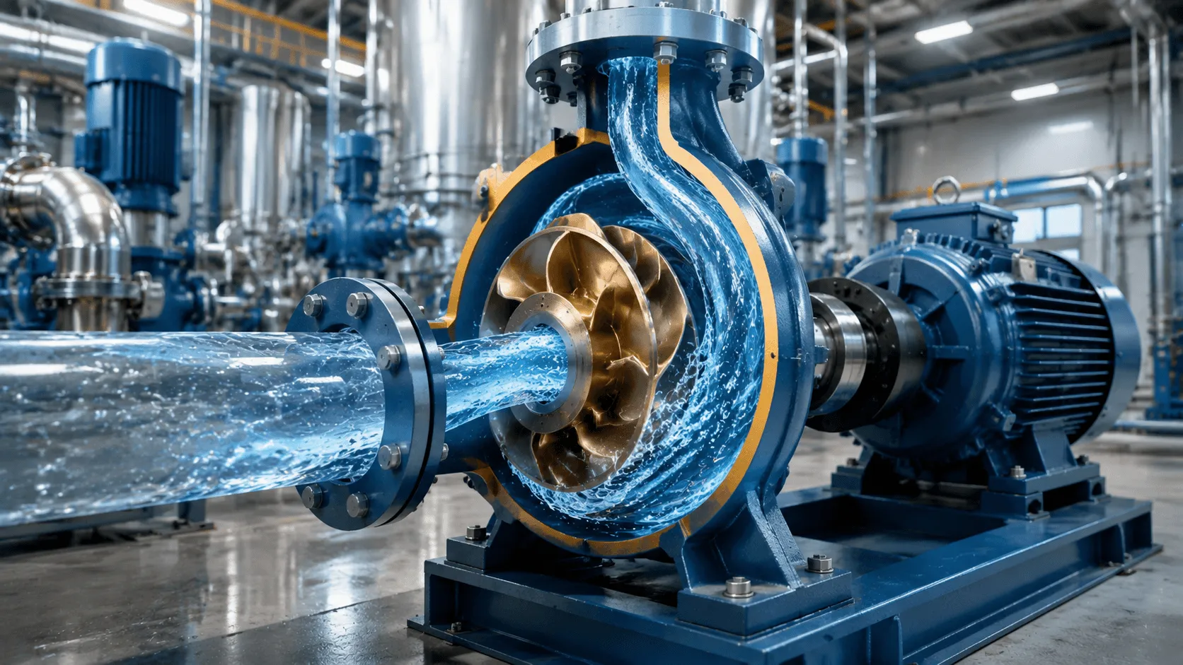
2026 centrifugal pump guide: principles (impeller, volute), performance (Q-H-η curves, BEP, NPSH), selection, industrial applications (chemical, power, water), maintenance & trends – TECHO expert solutions for efficiency & reliability.
Centrifugal Pump Technology: A Comprehensive Engineering Guide
As the core fluid-handling equipment in modern industry, centrifugal pumps drive the operation of chemical, power, water treatment, oil and gas, and agricultural production lines. With a market share of over 70% in the global industrial pump industry, their reliable operation directly determines production efficiency, energy consumption and operational costs.
Working Principles and Key Structural Components
Centrifugal pumps convert mechanical energy into fluid energy through the high-speed rotation of impellers, realizing the transfer and pressurization of liquids. Its working process is based on the law of conservation of energy and Bernoulli's principle, and the entire energy conversion process is completed in three core stages: fluid suction, energy transfer and pressure boosting.
1. Core Working Principles
When the pump is started, the motor drives the impeller to rotate at a fixed speed (1450 rpm for 4-pole motors and 2900 rpm for 2-pole motors for 50 Hz power supply), forming a low-pressure zone at the impeller inlet due to centrifugal force. Under the action of atmospheric pressure or upstream system pressure, the liquid is sucked into the impeller through the suction pipeline and suction chamber.
As the impeller rotates, the liquid particles are subjected to centrifugal acceleration, and the mechanical energy of the impeller is converted into the kinetic energy of the liquid (high velocity). The high-velocity liquid then enters the volute casing—a spiral structure with a gradually expanding cross-sectional area. The liquid velocity decreases sharply in the volute casing, and the kinetic energy is converted into static pressure energy to realize liquid pressurization.
💡 Key Operational Prerequisite: Centrifugal pumps are non-self-priming equipment. The pump cavity, suction pipeline and suction chamber must be fully filled with the conveyed liquid (priming) before startup. If air is trapped in the cavity, the pump will experience air binding—idling without delivering liquid, which will cause permanent damage to the pump in severe cases.
2. Key Structural Components & Their Functions
The performance and reliability of centrifugal pumps depend on the design and material selection of core components, each of which undertakes a specific role in the fluid handling process.
- Impeller: The core energy transfer component, divided into closed, semi-open and open types. Closed impellers with front and rear shrouds have high efficiency (suitable for clean liquids); semi-open/open impellers have good anti-clogging performance (suitable for slurries with solid particles).
- Volute Casing: Collects the high-velocity liquid from the impeller and converts kinetic energy into static pressure energy, with a gradually expanding cross-sectional area to minimize energy loss.
- Shaft and Bearing Assembly: Transmits torque from the motor to the impeller, with rolling bearings for small/medium pumps and sliding bearings for large high-speed pumps. Bearing temperature is a key monitoring indicator (the limit is 80°C for rolling bearings and 90°C for sliding bearings).
- Shaft Seal: Prevents liquid leakage from the gap between the rotating shaft and the stationary casing. Packing seals are low-cost and suitable for low-pressure non-toxic liquids; mechanical seals have high sealing performance and are widely used in high-pressure, high-temperature and corrosive fluid applications.
- Suction/Discharge Chamber: Guides the liquid to enter/exit the impeller smoothly, reducing the inlet/outlet pressure loss and optimizing the internal flow field of the pump.
Core Performance Parameters & Performance Curves
The performance of centrifugal pumps is characterized by a set of core parameters, which are the basis for pump selection, system design and operation adjustment. Understanding the definition, calculation method and mutual influence of these parameters is the key to avoiding mismatched selection and ensuring the pump operates in the optimal efficiency zone (BEP).
1. Five Core Performance Parameters
- Flow Rate (Q): The volume/mass of liquid delivered by the pump per unit time, the common unit is m³/h, L/s or US gpm. The actual flow rate is determined by the intersection of the pump performance curve and the system resistance curve.
- Head (H): The total energy obtained per unit weight of liquid through the pump, in meters (m), including static head, dynamic head and resistance head. The head of centrifugal pumps is independent of liquid density (except for high-viscosity liquids).
- Power & Efficiency (η): Shaft power is the input power of the motor to the pump shaft; hydraulic power is the effective power transferred to the liquid. Pump efficiency is the ratio of hydraulic power to shaft power, with industrial centrifugal pumps having an efficiency range of 60%–90% and high-efficiency models exceeding 95%.
- Net Positive Suction Head (NPSH): Divided into NPSHa (available) and NPSHr (required). To prevent cavitation, NPSHa must be 0.5–1.0 m higher than NPSHr, which is the golden rule for pump operation.
- Viscosity Adaptability: Designed for low-viscosity water-like liquids; when handling high-viscosity liquids (>100 cSt), the flow rate, head and efficiency will decrease significantly, and positive displacement pumps are recommended for replacement.
Hydraulic Power Calculation Formula
P_hydraulic (kW) = ρ × g × Q × H / 1000
Where: ρ = Liquid density (kg/m³) | g = 9.81 m/s² | Q = Flow rate (m³/h) | H = Head (m)
Pump Efficiency (η) = P_hydraulic / P_shaft × 100%
2. Performance Curves & Optimal Operation Point (BEP)
Manufacturers provide pump performance curves based on ISO standards, which depict the relationship between flow rate (Q) and head (H), efficiency (η), shaft power (P) and NPSHr under rated speed and 20°C clean water conditions. The Best Efficiency Point (BEP) is the peak of the efficiency curve, which is the optimal operating state of the pump.
Operating the pump outside the BEP (±10% of the BEP flow rate) will cause a series of problems: low flow rate operation will lead to increased vibration, noise and impeller wear; high flow rate operation will increase NPSHr demand and easily cause cavitation.
⚠️ Critical Operation Reminder: Do not operate the centrifugal pump with the discharge valve fully closed for a long time (no more than 5 minutes). Long-term no-load operation will cause the liquid in the pump cavity to generate heat due to friction, leading to liquid vaporization, seal damage and even pump casing deformation.
Typical Industrial Applications & Customized Design
Centrifugal pumps have strong adaptability to different liquids and working conditions. Through structural modification and material optimization, they can be applied to almost all industrial fields. The core of industrial pump selection is to match the pump performance with the medium characteristics and working conditions.
1. Water Treatment & Municipal Engineering
In municipal water supply and sewage treatment systems, centrifugal pumps are used for raw water extraction, water distribution, sewage lifting and sludge discharge. Raw water pumps adopt open impellers with anti-clogging design to handle suspended solids; submersible centrifugal pumps are used for sewage lifting to avoid priming operations; seawater desalination pumps use duplex stainless steel (2205/2507) or titanium alloy to resist seawater corrosion.
2. Power Generation & Oil and Gas Industry
In thermal power plants, boiler feedwater pumps (BFPs) are high-pressure core equipment with a head of up to 3000 m and a temperature of 280°C, adopting multi-stage centrifugal structure and variable frequency speed regulation. In the oil and gas industry, centrifugal pumps are used for crude oil extraction, refined oil transfer and circulating water cooling, with explosion-proof motors, high-temperature seals and wear-resistant impellers.
3. Chemical & Pharmaceutical Industry
Chemical and pharmaceutical processes involve a large number of corrosive, toxic and viscous liquids. Centrifugal pumps for this field adopt corrosion-resistant materials (Hastelloy, PTFE, PVDF) and magnetic drive seals (no shaft seal leakage) to ensure environmental safety and prevent medium contamination.
4. Agriculture & Food Processing
Agricultural centrifugal pumps focus on large flow rate and low head, with simple structure and corrosion-resistant casing to adapt to outdoor working environments. Food processing pumps adopt sanitary design (complying with 3A/FDA standards), with quick-dismantling structure for easy cleaning and sterilization.
| Industrial Field | Medium Characteristics | Recommended Material | Key Customization |
|---|---|---|---|
| Water Treatment | Clean water/sewage with suspended solids | Cast iron/304 stainless steel | Open impeller/anti-clogging design |
| Chemical Industry | Corrosive acid/alkali liquid | 316L stainless steel/Hastelloy | Magnetic drive seal/PTFE lining |
| Oil and Gas | Crude oil with sand/high-temperature oil | High-chromium cast iron/heat-resistant steel | Explosion-proof motor/wear-resistant impeller |
| Food Processing | Edible oil/dairy products/beverages | 316L stainless steel | Sanitary design/quick-dismantling structure |
Industrial Application Case: Chemical Plant Corrosive Fluid Transfer
A chemical plant in East Asia needed to transfer 30% sulfuric acid and alkaline mixtures (temperature 45°C, flow rate 20 m³/h, head 80 m). After replacing with centrifugal pumps with 316L stainless steel impeller/casing and corrosion-resistant mechanical seals, the equipment achieved stable operation for over 12 months with no abnormal leakage, cutting maintenance costs by 60%.
Advanced Maintenance Strategies & Fault Diagnosis
The maintenance of centrifugal pumps follows the principle of prevention first, prediction supplemented. Standardized routine maintenance and advanced predictive maintenance can significantly reduce unplanned downtime, extend pump service life and lower the whole life cycle cost.
1. Routine Inspection & Online Monitoring
- Vibration & Noise: Refer to ISO 10816 standard, vibration velocity ≤4.5 mm/s is normal. Abnormal vibration is caused by impeller imbalance, bearing damage, misalignment or cavitation.
- Temperature: Monitor bearing temperature and motor temperature in real time. Bearing temperature exceeding 80°C requires immediate inspection of lubrication and bearing wear.
- Seal Leakage: Packing seal leakage of 1–3 drops per second is normal; mechanical seal has no visible leakage under normal conditions.
- Pressure & Flow Rate: Real-time monitoring of inlet/outlet pressure and flow rate, deviation from the normal range indicates pipeline blockage or impeller wear.
- Lubricant State: Check the oil level and oil quality of the bearing box regularly, and the lubricant shall be free of emulsification, discoloration and impurities.
2. Key Maintenance Operations
- Lubrication Management: Oil-lubricated pumps change oil every 2000–4000 operating hours; grease-lubricated pumps refill grease every 1000–2000 operating hours.
- Seal Maintenance: Adjust the packing gland bolt evenly to avoid over-tightening; inspect the mechanical seal face for wear/scratches regularly.
- Impeller & Casing Maintenance: Clean the impeller and casing of scaling and deposits every 6–12 months; inspect the impeller for pitting corrosion and wear.
- Shutdown & Storage: Drain the liquid in the pump cavity for long-term shutdown; clean and apply anti-rust oil to key components.
3. Common Fault Diagnosis & Solution
🔧 Common Fault & Quick Solution
- No liquid delivery: Air binding/insufficient priming → Re-prime the pump and check for air leakage
- Low flow/head: Impeller wear/pipeline blockage → Clean the pipeline and replace the impeller
- Excessive vibration: Impeller imbalance/misalignment → Perform dynamic balance and align the pump and motor
- Seal leakage: Packing/mechanical seal damage → Replace the seal component
Future Development Trends of Centrifugal Pumps
With the development of industrial intelligence, energy conservation and environmental protection, centrifugal pumps are moving towards high efficiency, intelligence, customization and greenization. The combination of advanced design technology, new materials and IoT technology is reshaping the development pattern of the centrifugal pump industry.
- High-Efficiency Hydraulic Design: Adopt computational fluid dynamics (CFD) to optimize the impeller and volute casing structure, reduce flow loss, and develop ultra-high-efficiency pumps with efficiency exceeding 97%.
- Intelligent Operation & Predictive Maintenance: Integrate IoT, AI and big data technology to realize real-time monitoring, autonomous operation and predictive maintenance.
- Advanced Material Application: Develop new corrosion-resistant, wear-resistant and high-temperature resistant materials (ceramic matrix composites, high-entropy alloys) to adapt to harsher industrial working conditions.
- Leak-Free & Environmental Protection Design: Popularize magnetic drive seals and dry gas seals to eliminate liquid leakage; use biodegradable lubricants and IE5 ultra-high-efficiency motors.
- System Integration Optimization: From single pump optimization to pump system optimization, integrate pumps, pipelines, valves and control systems to improve the overall efficiency of the fluid handling system and reduce energy consumption by 10%–30%.
Master Centrifugal Pump Knowledge for Efficient Industrial Operation
Centrifugal pumps are the cornerstone of fluid handling in modern industry, and their scientific selection, standardized operation and proactive maintenance are the key to ensuring the stable and efficient operation of industrial production lines.
With the continuous innovation of industrial technology, the application of new materials, intelligent monitoring and efficient design will further improve the performance and reliability of centrifugal pumps.