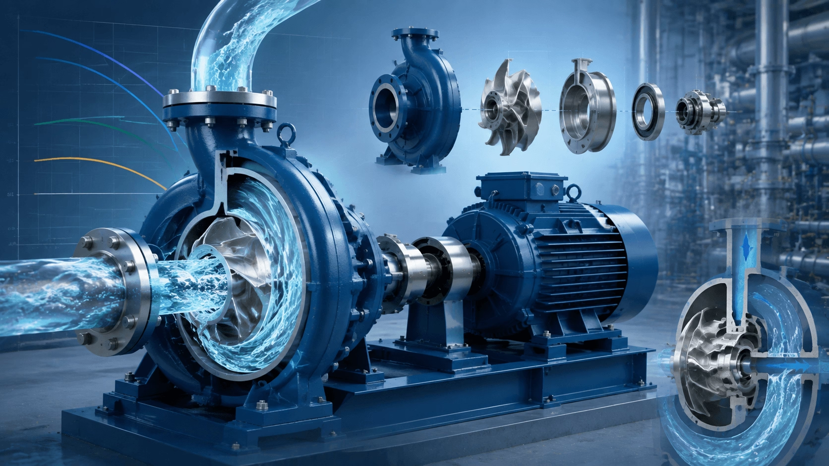
A comprehensive technical guide to centrifugal pump operation, encompassing fundamental principles, impeller design, casing configurations, NPSH requirements, performance curves, and primary industrial applications. Expert engineering insights from Techo Electrical & Mechanical (Titecho).
1. Introduction
The centrifugal pump is the most widely deployed pump typology globally, responsible for transporting approximately 90% of all pumped fluids across industrial, municipal, agricultural, and commercial sectors. From municipal water supply networks and HVAC cooling circuits to complex chemical processing and petroleum refining, centrifugal pumps dominate due to their straightforward construction, reliable operation, smooth flow delivery, and broad adaptability to diverse fluids and operational parameters.
Understanding the operational mechanics of these machines—encompassing both fundamental fluid physics and practical engineering design—is essential for professionals involved in fluid system architecture, operation, and maintenance.
2. Fundamental Operating Principles
2.1 Energy Conversion: Mechanical to Kinetic to Pressure
A centrifugal pump operates on a precise energy conversion sequence:
Mechanical Energy → Kinetic Energy → Pressure Energy
This process unfolds in three distinct stages:
- Impeller Rotation: The motor-driven impeller rotates at high velocity (typically 1,450–3,600 rpm), imparting tangential and radial velocity to the fluid entering at the impeller eye (centre).
- Velocity Head Generation: The fluid is accelerated radially outward through the impeller vanes, acquiring kinetic energy proportional to the square of the peripheral velocity.
- Velocity-to-Pressure Conversion: The pump casing (volute or diffuser) progressively decelerates the high-velocity fluid, converting kinetic energy into static pressure in accordance with Bernoulli's principle.
2.2 Centrifugal Force and Euler's Pump Equation
The theoretical head developed by an impeller is defined by Euler's turbomachinery equation:
H_theoretical = (u2 × cu2 - u1 × cu1) / g
Where:
- u1, u2 = Peripheral velocities at the inlet and outlet
- cu1, cu2 = Tangential components of the absolute fluid velocity
- g = Gravitational acceleration
For a standard radial-flow impeller where fluid enters axially (cu1 ≈ 0), the equation simplifies to:
H_theoretical = (u2 × cu2) / g
This relationship demonstrates that pump head is determined primarily by impeller diameter and rotational speed, rather than fluid density. Consequently, a centrifugal pump generates the same head (in metres) for water, oil, or chemical solutions, although the resulting pressure (in bar) and required brake horsepower vary proportionally with fluid density.
2.3 The Affinity Laws
The pump affinity laws dictate how performance parameters scale with variations in rotational speed and impeller diameter:
| Variable | Speed Change (N) | Diameter Change (D) |
|---|---|---|
| Flow Rate (Q) | Q ∝ N | Q ∝ D |
| Head (H) | H ∝ N² | H ∝ D² |
| Power (P) | P ∝ N³ | P ∝ D⁵ |
These laws form the mathematical foundation for variable-speed pump control and impeller trimming to optimise system performance.
3. Key Components and Their Functions
3.1 The Impeller: The Core Energy Transfer Element
The impeller is the rotating component that directly transfers mechanical energy to the fluid.
| Impeller Type | Geometry | Optimal Application | Characteristics |
|---|---|---|---|
| Closed (Shrouded) | Vanes enclosed between two shrouds | Clean liquids; high efficiency | Highest hydraulic efficiency; sensitive to solids |
| Semi-Open | Single shroud on one side | Liquids with moderate solids | Improved solids handling; slightly lower efficiency |
| Open | Vanes only, no shrouds | Slurries, sewage, abrasive fluids | Superior solids passage; lowest hydraulic efficiency |
| Radial Flow | Short, wide vanes | High head, low flow | Flat head curve; highly stable performance |
| Mixed Flow | Intermediate vane angle | Medium head, medium flow | Moderate specific speed applications |
| Axial Flow | Propeller-like blades | Low head, high flow | Steep head curve; power peaks at shut-off |
3.2 The Casing: Velocity to Pressure Conversion
| Casing Type | Design Configuration | Application | Efficiency Profile |
|---|---|---|---|
| Volute (Spiral) | Single or double spiral chamber | General-purpose; most common | Good; 10–15% of energy remains as velocity at discharge |
| Diffuser (Turbine) | Stationary vanes surrounding impeller | Multi-stage pumps; high specific speed | Higher than volute for specific high-head designs |
| Circular (Concentric) | Concentric chamber around impeller | Small pumps; solids handling | Lower; utilises simpler, more robust construction |
The volute's expanding cross-sectional area is engineered to ensure fluid velocity decreases uniformly, converting kinetic energy to pressure with minimal turbulence and internal recirculation.
3.3 Shaft, Bearings, and Mechanical Seals
| Component | Primary Function | Common Failure Modes |
|---|---|---|
| Shaft | Transmits torque from motor to impeller; supports radial/axial loads | Fatigue, corrosion, excessive deflection |
| Bearings | Support radial and thrust loads; maintain precise shaft alignment | Lubrication failure, contamination, EDM wear |
| Mechanical Seal | Prevents shaft leakage; maintains system pressure boundary | Face wear, dry running, chemical attack, thermal shock |
4. Performance Characteristics and Curves
4.1 The Pump Performance Curve
A centrifugal pump's operational envelope is defined by three interrelated curves:
| Curve | Description | Typical Shape |
|---|---|---|
| Head-Flow (H-Q) | Total dynamic head versus flow rate | Downward-sloping; profile varies by specific speed |
| Power-Flow (P-Q) | Brake horsepower versus flow rate | Rises continuously with flow for radial impellers |
| Efficiency-Flow (η-Q) | Hydraulic efficiency versus flow rate | Bell-shaped; peaks at the Best Efficiency Point (BEP) |
4.2 Best Efficiency Point (BEP)
The BEP represents the flow rate at which the pump achieves maximum hydraulic efficiency. Operating in proximity to the BEP is critical for mechanical reliability:
| Operating Region | Relative Flow | Operational Consequences |
|---|---|---|
| Near BEP | 80–110% of BEP | Optimal efficiency; minimal vibration; balanced radial loads |
| Left of BEP (Low Flow) | < 80% of BEP | Internal recirculation; overheating; thrust bearing overload |
| Right of BEP (High Flow) | > 110% of BEP | Cavitation risk; motor overload; excessive energy consumption |
Engineering Rule of Thumb: Continuous operation outside the 70–120% of BEP window significantly accelerates wear and reduces overall pump lifespan.
5. Net Positive Suction Head (NPSH)
5.1 NPSH Available vs. NPSH Required
NPSH Available (NPSHa) is a function of the system installation and fluid properties. NPSH Required (NPSHr) is established by the pump manufacturer via empirical testing, representing the minimum inlet pressure necessary to prevent cavitation.
5.2 Cavitation: The Destructive Phenomenon
Cavitation occurs when local static pressure drops below the fluid's vapour pressure, forming vapour cavities that collapse violently upon entering high-pressure zones within the impeller.
| Cavitation Stage | Observable Symptoms | Mechanical Damage |
|---|---|---|
| Incipient | Slight acoustic noise increase; < 3% head drop | None detectable via standard inspection |
| Moderate | Grinding noise; 3–10% head drop | Impeller pitting; rising vibration levels |
| Severe | Loud rumbling (sounds like pumping gravel); > 10% head drop | Severe impeller erosion; catastrophic seal and bearing failure |
Prevention Mandate: Maintain NPSHa ≥ NPSHr + 0.5 to 1.0 m safety margin across all anticipated operating conditions.
6. Common Industrial Applications
6.1 Water and Wastewater Treatment
| Application | Typical Pump Type | Key Engineering Considerations |
|---|---|---|
| Raw water intake | Horizontal split-case / vertical turbine | High flow capacity; debris handling; corrosion resistance |
| Booster stations | Multi-stage centrifugal | Variable demand management; stable pressure maintenance |
| Wastewater transfer | Submersible / non-clog dry-pit | Solids passage capability; ragging resistance |
| Sludge handling | Open-impeller centrifugal | High viscosity tolerance; abrasive solids handling |
6.2 HVAC and Building Services
| Application | Configuration | Efficiency Focus |
|---|---|---|
| Chilled water circulation | End-suction / inline | VFD part-load optimisation |
| Cooling tower | Vertical inline / horizontal split-case | Low NPSHr requirements; corrosion-resistant materials |
| Hot water heating | High-temperature mechanical seal design | Thermal expansion management |
| Pressure boosting | Multi-stage vertical inline | Compact footprint; low acoustic emission |
6.3 Heavy Industrial Process
| Industry | Application | Special Requirements |
|---|---|---|
| Oil & Gas | Pipeline transfer; refining | API 610 compliance; high temperature; sour service (NACE) |
| Chemical | Acid transfer; polymer circulation | Exotic alloy materials; chemical seal compatibility |
| Food & Beverage | CIP cleaning; sanitary product transfer | 3-A / EHEDG sanitary certification; polished finishes |
| Power Generation | Boiler feed; circulating cooling water | Extreme high pressure; redundant, highly reliable design |
| Mining | Slurry transport; mine dewatering | Extreme abrasion resistance; thick reinforced casings |
7. Selection and Sizing Guidelines
7.1 The Systematic Selection Process
- Define Fluid Properties: Document density, viscosity, temperature, solids content, and chemical compatibility.
- Determine Duty Requirements: Calculate required flow rate, total dynamic head (TDH), and available NPSH.
- Select Pump Type: Base selection on specific speed, solids handling requirements, and spatial constraints.
- Size the Drive Motor: Ensure non-overloading characteristics to the end of the curve; apply the appropriate service factor.
- Verify Materials: Confirm long-term compatibility between wetted components, the pumped fluid, and the ambient environment.
- Validate Operating Range: Confirm stable, continuous operation in close proximity to the BEP.
7.2 Material Selection Matrix
| Fluid / Environment | Common Materials | Engineering Notes |
|---|---|---|
| Clean water | Cast iron, bronze-fitted | Standard, cost-effective construction |
| Seawater / corrosive | Duplex stainless steel, Ni-Al-Bronze | Cathodic protection highly recommended |
| Abrasive slurries | High-chrome iron, rubber-lined | High surface hardness for severe abrasion |
| High temperature | Carbon steel casing; 12% Cr impeller | Custom thermal expansion clearances required |
| Food grade | 316L stainless steel | FDA compliant, polished sanitary finish |
8. Maintenance and Troubleshooting
8.1 Common Operational Anomalies and Corrective Actions
| Symptom | Likely Root Causes | Corrective Action |
|---|---|---|
| No flow | Unprimed pump; incorrect rotation; suction blockage | Prime pump; verify phase sequence; clean suction strainer |
| Low flow | Impeller wear; system restrictions; air entrainment | Inspect wear rings; adjust discharge valves; seal air leaks |
| Low head/pressure | Worn impeller; excessive internal clearance; low speed | Replace components; verify motor frequency and RPM |
| Excessive vibration | Misalignment; imbalance; cavitation; bearing wear | Perform laser alignment; balance rotor; resolve NPSH deficit |
| Overheating | Minimum flow operation; dry running; bearing failure | Install automatic bypass line; inspect seals; replace bearings |
| Seal leakage | Face damage; O-ring degradation; shaft misalignment | Replace cartridge seal; realign pump and driver |
9. Conclusion
The dominance of the centrifugal pump in global fluid handling is the direct result of a fundamentally efficient energy conversion process, robust mechanical construction, and extraordinary adaptability across diverse applications and scales. From basic impeller dynamics and volute pressure conversion to critical NPSH control, advanced material engineering, and precise system curve matching, centrifugal pumps represent mature, highly reliable fluid machinery optimised for modern industrial demands.
Successful pump performance relies fundamentally on system-level engineering: selecting the correct pump typology, maintaining stable operation near the Best Efficiency Point, eliminating cavitation risks, and implementing scheduled predictive maintenance. When properly specified and maintained, centrifugal pumps deliver decades of low-cost, continuous service across water treatment, HVAC, chemical processing, power generation, and agricultural sectors.
Reference Standards:
For industry standards and technical validation, consult the Hydraulic Institute (ANSI/HI), API 610, ISO 5199, NACE corrosion guidelines, and official manufacturer application manuals to ensure long-term pump reliability and regulatory compliance.
10. Engineered Pump and Drive Solutions with Titecho
Techo Electrical & Mechanical (Taizhou) Co., Ltd. (Brand: Titecho) specialises in the design and manufacture of high-efficiency electric motors and integrated drive systems engineered specifically for demanding centrifugal pump applications. Our product portfolio features premium copper windings, IE3/IE4 high-efficiency classifications, advanced bearing protection, and robust mechanical constructions tailored to the rigorous demands of municipal, industrial, and commercial fluid systems.
We provide comprehensive engineering support, including system curve analysis, NPSH verification, pump-motor matching, VFD integration guidance, and total cost of ownership (TCO) modelling to ensure optimal system performance and lifecycle reliability.
Explore technical data sheets, performance curves, and application engineering support at www.cntecho.com.
© Techo Electrical & Mechanical (Titecho) – Precision Fluid Handling and Electromechanical Excellence