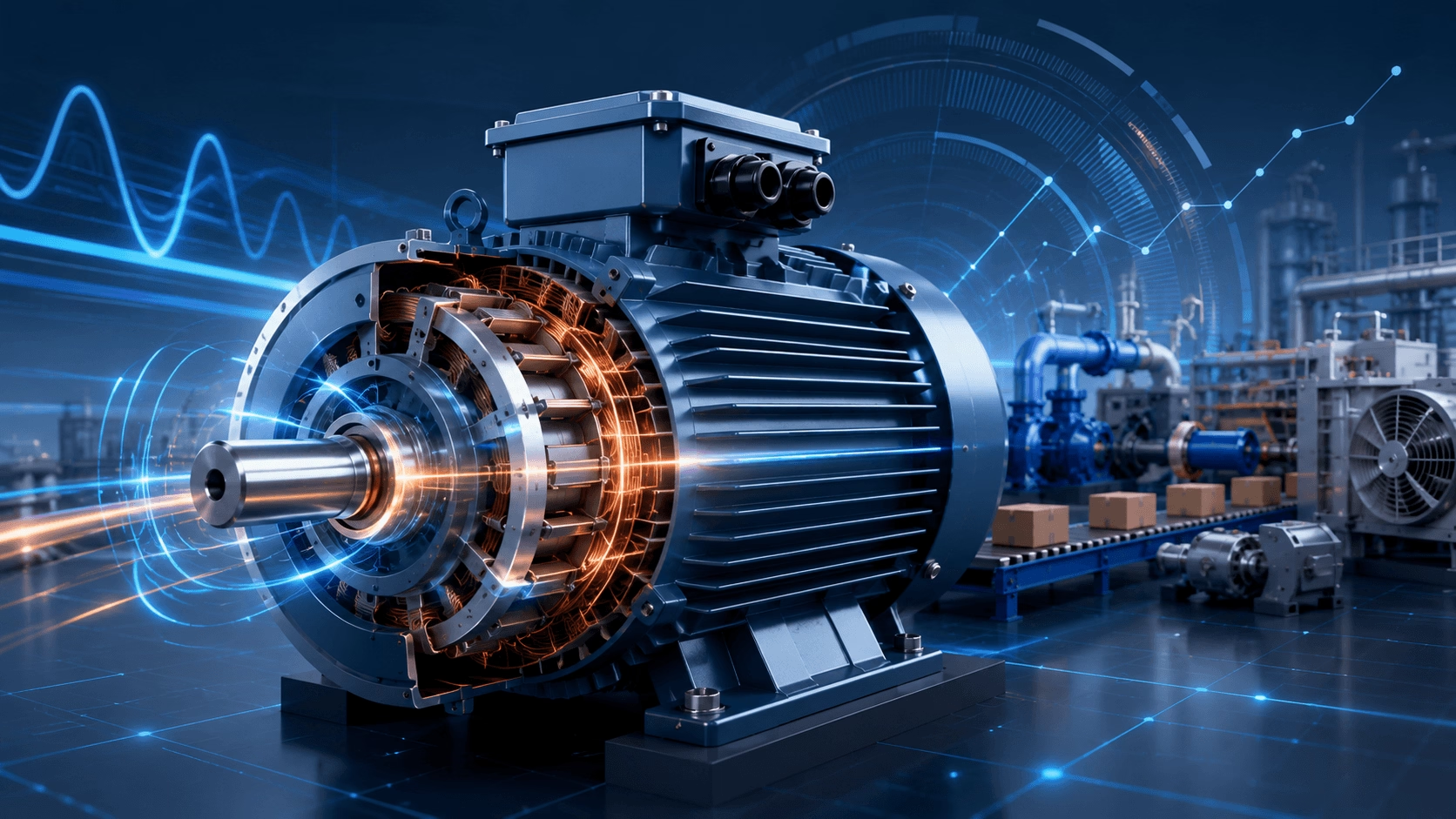
2026 AC Motor Torque Guide: Rated/starting/max torque dynamics, torque-speed curve analysis, the Kloss formula, precise load matching (pumps/fans/conveyors/high-inertia), advanced VFD/FOC/DTC control architectures, influencing factors, and optimization strategies for IE5 efficiency and reliability — compiled with TECHO industrial engineering expertise.
Introduction: Torque as the Electromechanical Bridge
Torque is the fundamental mechanical output of an AC motor, representing the rotational force that drives industrial machinery, commercial equipment, and precision automation systems. In the context of 2026's Industry 4.0 landscape, where digital twins and AI-driven predictive maintenance are standard, torque is no longer just a static nameplate specification; it is a dynamic, continuously monitored variable that dictates system health, energy efficiency, and process quality.
A comprehensive understanding of AC motor torque characteristics—including electromagnetic generation principles, mechanical performance curves, load matching requirements, and advanced control methodologies—is essential for engineers, system designers, and maintenance professionals. This guide provides a rigorous, science-based analysis of AC motor torque, empowering you to optimize drive system performance, ensure operational reliability, and maximize energy efficiency in modern electromechanical applications.
Fundamental Concepts: Defining AC Motor Torque
Unlike linear force, torque represents rotational force—the product of force and the perpendicular distance from the axis of rotation. In AC motor applications, torque is the critical parameter that determines a motor's ability to start, accelerate, and maintain operation under mechanical load.
1. Rated Torque (T_N): The Nameplate Specification
The rated torque (T_N) is the continuous torque output the motor can deliver at rated voltage, frequency, and ambient conditions (typically 40°C) without exceeding thermal limits under continuous duty (S1). It is derived directly from the motor's nameplate power and speed ratings:
T_N = 9550 × P_N / n_N
Parameter Explanation:
T_N= Rated torque (N·m)P_N= Rated power (kW)n_N= Rated speed (r/min)9550= Constant derived from unit conversion: 60,000 / (2 × π)
2. Starting Torque (T_st): Breakaway Capability
The starting torque (also called locked-rotor torque) is the torque produced at zero speed (n = 0) when rated voltage and frequency are applied. This parameter is critical for applications with high static friction or massive inertia, such as loaded conveyors, crushers, and large fans. International standards (IEC Design N/H and NEMA Design B/C/D) specify different T_st/T_N ratios to match specific application breakaway requirements.
3. Maximum Torque (T_max): The Stability Limit
The maximum torque (breakdown torque) represents the peak torque capability of the motor before stall occurs. For standard squirrel-cage induction motors, T_max typically ranges from 200% to 300% of rated torque. This margin provides:
- The ability to handle temporary, severe overloads without stalling.
- A stability margin against sudden supply voltage fluctuations.
- Sufficient acceleration capability for high-inertia loads.
4. Pull-Up Torque (T_pu): The Acceleration Minimum
The pull-up torque is the minimum torque developed during acceleration from standstill to the speed at which maximum torque occurs. In NEMA Design B motors, this represents the torque "valley" during startup. It is absolutely critical that the pull-up torque exceeds the load torque at all points during this acceleration phase; otherwise, the motor will stall in the "pull-up valley" and never reach full speed.
Electromagnetic Torque Generation: The Physics of Rotation
The production of torque in AC motors is fundamentally an electromagnetic phenomenon governed by the interaction between magnetic fields and current-carrying conductors.
Induction Motor Torque Production
In three-phase induction motors, the stator windings create a rotating magnetic field (RMF) with a synchronous speed:
n_s = 60 × f / p
(Where f = supply frequency in Hz, p = number of pole pairs)
This rotating field induces currents in the rotor conductors through electromagnetic induction. The interaction between the stator field and rotor currents produces torque according to the exact equivalent circuit equation:
T = (3 × V² × R'₂/s) / [ω_s × ((R₁ + R'₂/s)² + (X₁ + X'₂)²)]
Parameter Explanation:
V= Phase voltage (V)s= Slip (dimensionless)R'₂= Rotor resistance referred to the stator (Ω)X'₂= Rotor reactance referred to the stator (Ω)R₁, X₁= Stator resistance and leakage reactance (Ω)ω_s= Synchronous angular velocity (rad/s)
The Kloss Formula: Simplified Torque-Slip Relationship
For practical engineering calculations and plotting torque-speed curves, the Kloss formula provides an excellent approximation of the torque-slip characteristic:
T / T_max = 2 / (s/s_max + s_max/s)
Key Insight: This formula reveals that maximum torque (T_max) is independent of rotor resistance, while the slip at which maximum torque occurs (s_max) is directly proportional to rotor resistance (s_max ≈ R'₂ / X'₂). This principle is the foundational mechanism for controlling wound-rotor motors via external rotor resistance.
Synchronous Motor Torque Characteristics (PMSM & SynRM)
In 2026, Permanent Magnet Synchronous Motors (PMSMs) and Synchronous Reluctance Motors (SynRMs) dominate the IE5 ultra-premium efficiency market. They produce torque through the magnetic locking between the rotor field and the stator rotating field. The general torque equation for an interior permanent magnet (IPM) or PM-assisted SynRM includes both magnetic and reluctance components:
T = (3/2) × p × [Ψ_PM × i_q + (L_d - L_q) × i_d × i_q]
Parameter Explanation:
p= Number of pole pairsΨ_PM= Permanent magnet flux linkage (Wb)i_d, i_q= Direct-axis and quadrature-axis currents (A)L_d, L_q= Direct-axis and quadrature-axis inductances (H)
Synchronous motors maintain constant speed regardless of load (up to the pull-out torque limit) and offer superior efficiency and power factor characteristics compared to induction motors.
The Torque-Speed Characteristic Curve (T-n Curve)
The torque-speed characteristic curve is the fundamental performance fingerprint of an AC motor. It defines the motor's operational capabilities across its entire speed range and is essential for proper motor-load matching.
Key Operating Regions of the T-n Curve
| Operating Region | Speed Range | Torque Characteristic | Application Significance |
|---|---|---|---|
| Starting (Locked Rotor) | n = 0 (s = 1) | T = T_st (starting torque) | Must exceed load static friction; critical for breakaway. |
| Acceleration | 0 < n < n_maxT | T increases to T_max | Motor torque must exceed load torque throughout the entire acceleration phase. |
| Maximum Torque (Breakdown) | n = n_maxT (s = s_max) | T = T_max (breakdown torque) | The absolute stability limit; operation beyond this point causes immediate stall. |
| Rated Operation | n = n_N (s = s_N ≈ 0.02) | T = T_N (rated torque) | The continuous duty design point; the region of maximum efficiency. |
| Field Weakening (Constant Power) | n > n_N (s < 0) | T decreases as 1/n | Used in VFDs to extend speed range above base speed; torque drops to maintain constant power. |
| No-Load | n ≈ n_s (s ≈ 0) | T ≈ 0 (friction/windage only) | Synchronous speed is approached asymptotically; zero useful torque production. |
NEMA and IEC Design Classifications
Standardization bodies define specific torque-speed characteristics to match motors to application requirements:
- NEMA Design B / IEC Design N: General purpose. Normal starting torque (150-200% T_N), low starting current. Suitable for 80% of industrial applications: fans, pumps, compressors.
- NEMA Design C / IEC Design H: High starting torque (200-250% T_N). Suitable for heavily loaded conveyors, crushers, and agitators with high starting friction.
- NEMA Design D: Very high starting torque (275% T_N+), high slip (5-13%). Suitable for punch presses, hoists, and loads with high intermittent peak demands.
Load Torque Characteristics and Motor Matching
Successful drive system design requires matching the motor's torque-speed capability to the load's torque demand across the entire operating range. Load characteristics fundamentally dictate motor selection and control strategy.
Classification of Load Torque Characteristics
Type 1: Constant Torque Loads
- Relationship:
T_L = Constant(independent of speed) - Power Relationship:
P ∝ n(power increases linearly with speed) - Examples: Conveyors, hoists, cranes, positive displacement pumps, reciprocating compressors, extruders.
- Motor Selection: Requires high starting torque capability. Continuous rated torque must equal or exceed load torque. Thermal capacity for full-load operation at all speeds (requires forced cooling if operating at low speeds via VFD).
Type 2: Variable Torque (Quadratic) Loads
- Relationship:
T_L ∝ n²(torque proportional to speed squared) - Power Relationship:
P ∝ n³(power proportional to speed cubed - Affinity Laws) - Examples: Centrifugal pumps, centrifugal fans, blowers, propellers.
- Motor Selection: Lower starting torque is acceptable. Massive energy savings potential with variable speed operation. The motor is often significantly oversized at reduced speeds.
Type 3: Constant Power Loads
- Relationship:
P = Constant, thereforeT ∝ 1/n(torque inversely proportional to speed) - Examples: Machine tool spindles, wire winding/unwinding, traction drives, rolling mills.
- Motor Selection: Requires an extended constant power speed range. Field weakening operation is necessary. Special consideration for thermal management at low speeds where high torque is required.
The Motor-Load Matching Criterion
For reliable operation, the motor torque capability must strictly exceed the load torque demand at all operating points:
T_motor(n) > T_load(n) for all n in the operating range.
Furthermore, the acceleration requirement is governed by Newton's second law for rotation:
T_motor(n) - T_load(n) = J_total × (dn/dt)
(Where J_total = total moment of inertia of the motor, coupling, and load)
The acceleration torque margin (the difference between motor torque and load torque) determines the system's dynamic response. Insufficient margin results in prolonged starting times, excessive rotor heating, or failure to reach full speed.
Advanced Torque Control Technologies
Modern power electronics, particularly Silicon Carbide (SiC) inverters, and advanced control algorithms have revolutionized AC motor torque control, enabling precise, dynamic torque response previously achievable only with DC drives.
1. Variable Frequency Drive (VFD) Scalar Control (V/f)
The fundamental VFD control method maintains constant magnetic flux by preserving the voltage-to-frequency ratio:
V / f = Constant (below base speed)
- Torque Capability: Approximately constant up to base speed; constant power above base speed.
- Limitations: While simple and robust, scalar control lacks precise torque control because it regulates only magnitude, not the phase relationship between voltage and current. It suffers from poor low-speed torque and slow dynamic response. Suitable for basic pump/fan applications.
2. Field Oriented Control (FOC) / Vector Control
FOC transforms three-phase AC quantities into a rotating reference frame (d-q coordinates) aligned with the rotor flux, enabling independent, decoupled control of flux-producing current (i_d) and torque-producing current (i_q).
- Key Advantages: Full rated torque available from zero speed; torque response time of 1-5 ms; precise speed and position control through cascaded PID loops.
- 2026 Trend: Closed-loop FOC with high-resolution absolute encoders is the standard for precision robotics and CNC spindle drives.
3. Direct Torque Control (DTC)
DTC eliminates traditional current controllers and PWM modulators, directly controlling stator flux and torque through optimal voltage vector selection based on high-frequency hysteresis comparators.
- Torque Response: < 1 ms (the fastest among industrial drives).
- Robustness: Highly robust to motor parameter variations. Does not require a rotor position sensor for induction motors (sensorless operation).
- Applications: Preferred for high-power applications (MW range), traction drives, and applications requiring maximum dynamic performance and zero-speed full torque.
4. Sensorless Vector Control & AI Observers
Advanced algorithms estimate rotor position and speed purely from measured stator voltages and currents, eliminating physical encoders and their associated maintenance.
- Flux Observers & MRAS: Model Reference Adaptive Systems compare a reference model with an adjustable model to estimate speed.
- High-Frequency Injection: Injects a high-frequency voltage signal to detect rotor saliency, enabling full-torque operation at zero speed in IPMSM and SynRM motors.
- 2026 AI Integration: Modern drives utilize Machine Learning algorithms to continuously auto-tune observer parameters, compensating for motor thermal drift and aging without manual commissioning.
Factors Affecting Actual Torque Output
The torque delivered by an AC motor in actual operation deviates from theoretical predictions due to various electrical, thermal, and mechanical factors.
1. Supply Voltage Variations
Torque is strictly proportional to the square of the applied voltage:
T ∝ V²
A mere 10% voltage reduction results in a 19% torque reduction. This quadratic relationship makes voltage stability absolutely critical for applications with high starting torque requirements or narrow stability margins.
2. Temperature and Thermal Effects
Increased winding temperature raises electrical resistance:
R_hot = R_cold × [1 + α × (T_hot - T_cold)]
(Where α = 0.00393 /°C for copper)
Higher rotor resistance reduces starting torque but increases slip at rated load. Furthermore, in PMSM motors, excessive temperature can cause partial demagnetization of the permanent magnets, leading to irreversible torque loss.
3. Harmonic Distortion and PWM Ripple
VFDs introduce harmonic voltages and high-frequency switching transients (dV/dt) that:
- Create additional harmonic torques (pulsating components), causing torque ripple.
- Increase stray load losses and reduce average torque capability.
- Cause mechanical vibration and acoustic noise.
Note: The adoption of SiC inverters in 2026 allows for much higher switching frequencies, significantly smoothing the current waveform and reducing torque ripple compared to legacy IGBT drives.
4. Mechanical System Considerations
The mechanical transmission system directly affects torque delivery:
- Gearbox Efficiency: Reduces available torque at the load (typically 3-5% loss per gear stage).
- Coupling Alignment: Misalignment creates reactive radial forces, increasing bearing friction and reducing effective torque transmission.
- Torsional Resonance: If the excitation frequency (e.g., VFD switching or load pulsation) matches the mechanical natural frequency of the shaft system, severe torque amplification and shaft failure can occur.
Torque Measurement and Verification
Accurate torque measurement is essential for performance verification, quality control, and advanced condition monitoring.
Direct Torque Measurement Methods
- Strain Gauge Torque Transducers: Bonded foil strain gauges on a torsion shaft provide high accuracy (±0.1%) and wide bandwidth. Require slip rings or wireless telemetry for rotating applications.
- Optical Torque Sensors: Measure the phase shift (twist angle) between two coded discs on the shaft. Non-contact and immune to electromagnetic interference.
- Surface Acoustic Wave (SAW) Sensors: Wireless, passive sensors suitable for harsh, high-voltage environments; limited temperature range but require no internal power source.
Indirect Torque Estimation (Digital Twin Approach)
When direct measurement is impractical, torque is estimated in real-time from electrical measurements using the air-gap torque equation:
T_ag = (3/2) × p × (Ψ_α × i_β - Ψ_β × i_α)
(Where Ψ_α, Ψ_β = stator flux linkages; i_α, i_β = stator currents in the stationary reference frame)
This method, embedded in modern motor protection relays and VFDs, enables continuous, non-intrusive torque monitoring, forming the basis for predictive maintenance algorithms.
Common Torque-Related Issues and Solutions
| Issue | Symptoms | Engineering Solutions |
|---|---|---|
| Insufficient Starting Torque | Motor fails to start, stalls, or accelerates too slowly; excessive starting current duration. | Verify actual voltage at motor terminals under load; select NEMA Design C or D motor; implement VFD for controlled high-torque acceleration; check for mechanical binding. |
| Torque Pulsation & Vibration | Mechanical vibration at specific speeds; audible acoustic noise; fatigue failures in couplings. | Avoid continuous operation near mechanical resonant speeds; check for broken rotor bars (via MCSA); optimize VFD carrier frequency and switching patterns; install torsional vibration dampers. |
| Thermal Overload Under Torque | Motor trips on thermal protection; insulation degradation; shortened bearing life. | Verify actual load torque profile against motor capability curve; implement proper IEC 60255-8 thermal replicas in protection relays; install forced independent ventilation (IC416) for low-speed VFD operation. |
| Low-Speed Torque Drop (VFD) | Motor stalls or lacks torque when operating below 10 Hz with scalar control. | Switch from V/f scalar control to Sensorless Vector Control (SVC) or Closed-Loop FOC; ensure motor is rated for inverter duty with reinforced insulation. |
Engineering Best Practices for Torque Optimization
Motor Selection Guidelines
- Calculate the Load Torque Profile: Determine T_L(n) across the entire operating range, including starting, acceleration, and steady-state conditions. Do not rely on nominal values alone.
- Apply Safety Margins:
T_motor ≥ 1.1 × T_loadfor steady-state;T_st,motor ≥ 1.25 × T_st,loadfor reliable breakaway. - Verify Thermal Capacity: Ensure the RMS torque over the entire duty cycle does not exceed the rated torque. Consider the service factor for intermittent or highly cyclic duty.
- Evaluate Stability Margin: Ensure
T_max / T_ratedis sufficient to accommodate expected voltage dips (typically 10-20%) without stalling.
System Integration Considerations
- Inertia Matching: The load inertia (J_load) should generally not exceed 10× the motor inertia (J_motor) for standard induction motors to ensure stable control. Higher ratios (up to 50x) are acceptable with modern VFDs and FOC, but require careful tuning.
- Torsional Analysis: For high-power or high-speed systems, perform a torsional analysis to map mechanical natural frequencies and avoid torsional resonance during acceleration.
- Regenerative Capability: For overhauling loads (e.g., downhill conveyors, descending elevators) or rapid deceleration, specify active front-end (AFE) drives or braking resistors to safely handle negative torque and regenerative energy.
Conclusion: Mastering Torque for Optimal Drive Performance
AC motor torque is far more than a simple specification parameter—it is the dynamic, physical interface between electrical energy and mechanical work. Mastery of torque fundamentals, from electromagnetic generation principles through advanced digital control strategies, distinguishes competent drive system design from exceptional, future-proof engineering.
The key insights from this comprehensive 2026 analysis include:
- Torque capability must be evaluated across the entire speed range, not just at rated conditions.
- Load torque characteristics fundamentally dictate motor selection, enclosure cooling, and control strategy.
- Modern electronic control (FOC, DTC, AI-observers) transforms AC motor torque performance, enabling high-dynamic applications previously impossible with line-fed operation.
- Thermal management, voltage stability, and mechanical torsional integrity are just as critical as raw torque magnitude for reliable, long-term operation.
By applying the principles, calculations, and best practices detailed in this guide, engineers can ensure that AC motor drive systems deliver optimal torque performance—maximizing productivity, minimizing energy consumption, and achieving design-life reliability in even the most demanding industrial environments.
Optimize Your Torque Performance with Expert Engineering Support
Achieving optimal torque performance requires more than selecting a motor from a catalog—it demands systematic analysis of load characteristics, operating environment, and advanced control requirements.
Our team of certified electrical and mechanical engineers provides comprehensive torque analysis, motor selection validation, and drive system optimization services. From initial specification and torsional analysis through commissioning and AI-driven performance monitoring, we partner with you to ensure your AC motor systems deliver the exact torque, efficiency, and reliability your applications demand.
Contact Our Engineering Team to secure your drive system's performance and reliability.
© 2026 TECHO Industrial Engineering Solutions. All rights reserved. This document is intended for professional engineering reference. All motor selections and drive system designs must be validated by a qualified engineer in accordance with applicable local electrical codes, IEC 60034, NEMA MG 1, and site-specific safety regulations.