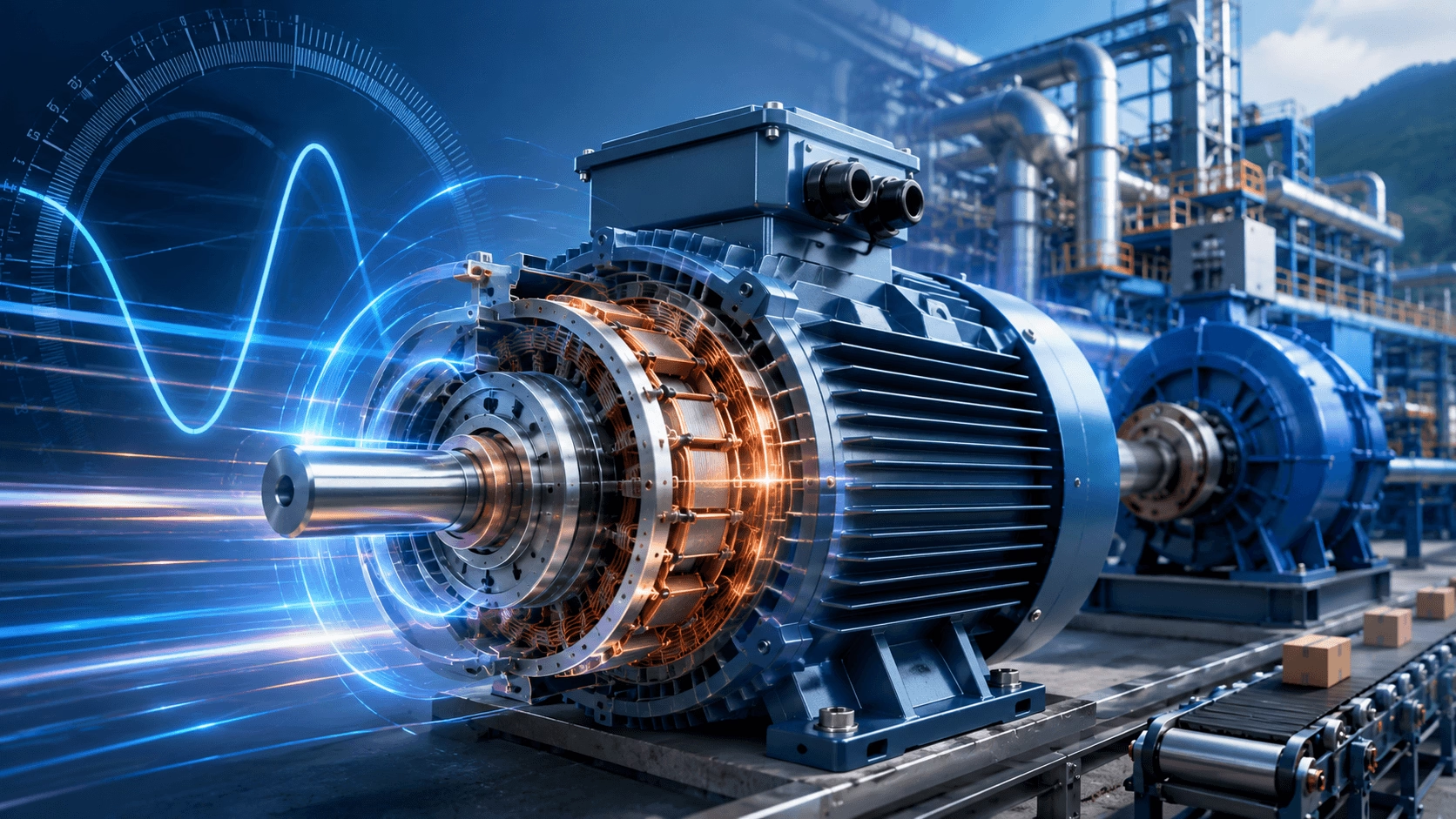
2026 AC Motor Speed Characteristics Analysis: Synchronous speed dynamics, slip mechanics, torque-speed profiling, advanced VFD/Vector control (FOC/DTC), stability regulation, affinity laws for pumps/fans, and future technological trends — compiled with TECHO engineering expertise.
Introduction: The Evolution of AC Motor Speed Control
The speed of an AC motor is fundamentally determined by the frequency of the applied power supply and the number of magnetic poles in the motor's stator winding. Unlike DC motors, where speed is primarily controlled by armature voltage, AC motor speed is inherently linked to the rotating magnetic field (RMF) speed, known as synchronous speed. This relationship forms the theoretical foundation for understanding all AC motor speed characteristics and control methodologies.
In the modern industrial landscape of 2026, the distinction between synchronous speed and actual rotor speed—known as slip—remains the defining characteristic that differentiates various AC motor types and determines their speed-torque performance profiles. However, the advent of Silicon Carbide (SiC) inverters, AI-driven predictive control, and IE5 ultra-premium efficiency motors has transformed AC motors from simple fixed-speed devices into highly dynamic, digitally controllable electromechanical systems.
1. Fundamental Principles of AC Motor Speed
The rotational speed of an AC motor is a direct function of the electrical frequency supplied to the stator and the physical geometry of the magnetic circuit.
- Synchronous Speed (n_s): The theoretical speed of the rotating magnetic field generated by the stator windings.
- Rotor Speed (n_r): The actual mechanical speed of the rotor shaft.
- Slip (s): The necessary speed differential between the RMF and the rotor, which enables electromagnetic induction and torque production in asynchronous (induction) motors.
Understanding the interplay between these three variables is non-negotiable for engineers tasked with optimizing drive system performance, ensuring operational reliability, and maximizing energy efficiency.
2. Synchronous Speed Theory and Calculation
2.1 Fundamental Synchronous Speed Equation
Synchronous speed represents the rotational velocity of the stator's magnetic field and is calculated using the universal AC motor formula:
n_s = (120 × f) / P
Parameter Explanation:
- n_s = Synchronous speed (Revolutions Per Minute, RPM)
- f = Supply frequency (Hertz, Hz)
- P = Number of magnetic poles (must be an even integer: 2, 4, 6, 8...)
- 120 = Dimensional constant derived from converting electrical cycles to mechanical revolutions (60 seconds/minute × 2 pole pitches per cycle).
Example Calculation: For a 4-pole motor operating on a standard 60 Hz North American supply:
n_s = (120 × 60) / 4 = 1,800 RPM
2.2 Standard Synchronous Speeds by Pole Count
The following table presents standard synchronous speeds for common pole configurations at both 60 Hz and 50 Hz global supply frequencies:
| Pole Count (P) | 60 Hz Speed (RPM) | 50 Hz Speed (RPM) | Typical Applications |
|---|---|---|---|
| 2 | 3,600 | 3,000 | High-speed pumps, fans, machine tool spindles |
| 4 | 1,800 | 1,500 | General industrial, HVAC, centrifugal pumps |
| 6 | 1,200 | 1,000 | Conveyors, crushers, mixers, agitators |
| 8 | 900 | 750 | Heavy-duty crushers, ball mills, kilns |
| 10 | 720 | 600 | Large ventilation fans, multi-stage compressors |
| 12 | 600 | 500 | High-torque, low-speed direct-drive applications |
2.3 Synchronous Motor Operation
True synchronous motors (including Permanent Magnet Synchronous Motors - PMSMs, and Synchronous Reluctance Motors - SynRMs) operate at exactly synchronous speed (n = n_s) with zero slip. These motors require a DC excitation of the rotor (via permanent magnets or external slip rings) to physically lock the rotor to the rotating stator field. Synchronous motors maintain constant speed regardless of load (up to the pull-out torque limit) and can provide power factor correction by operating at leading power factors, making them the gold standard for IE5 efficiency applications in 2026.
3. Slip and Asynchronous Motor Speed
3.1 Slip Fundamentals
Induction motors (the most common AC motor type globally) operate asynchronously, meaning the rotor turns slightly slower than the synchronous speed. This speed difference, called slip, is absolutely essential for torque production—rotor currents are induced only by the relative motion between the rotating field and the rotor conductors.
Slip (s) = (n_s - n_r) / n_s
(Expressed as a decimal or multiplied by 100 for a percentage)
The actual rotor speed is derived as:
n_r = n_s × (1 - s)
3.2 Typical Slip Values by Motor Design
NEMA and IEC standards define several motor design classifications based on speed-torque characteristics and slip behavior:
| NEMA / IEC Design | Full-Load Slip | Starting Torque | Typical Applications |
|---|---|---|---|
| Design A / N | 0.5 - 3% | High | High-inertia loads, momentary overloads |
| Design B / N | 0.5 - 3% | Normal | General purpose, pumps, fans (Most Common) |
| Design C / H | 1 - 5% | Very High | Hard-to-start loads, loaded conveyors, crushers |
| Design D | 5 - 8%+ | Highest | High-inertia loads, punch presses, shears |
3.3 Slip and Motor Performance Diagnostics
Slip is directly related to motor torque production, efficiency, and thermal health:
- Slip Frequency: The frequency of induced rotor currents equals the slip frequency:
f_slip = s × f_supply. At 5% slip and 60 Hz, rotor currents flow at just 3 Hz. - Slip Losses: Power dissipated as heat in the rotor resistance equals slip times the air-gap power:
P_slip = s × P_gap. At 5% slip, 5% of the developed mechanical power is lost as rotor heat. - Speed Regulation: The change in speed from no-load to full-load, typically 2-4% for NEMA B motors.
💡 TECHO Diagnostic Insight:
In 2026, modern VFDs continuously calculate slip in real-time. An unexpected increase in full-load slip (e.g., rising from 2.5% to 6%) without a corresponding increase in mechanical load is a primary indicator of degraded rotor bars, stator winding shorts, or severe mechanical binding, enabling predictive maintenance before catastrophic failure.
4. Speed-Torque Characteristics
4.1 Torque-Speed Curve Analysis
The torque-speed curve defines a motor's mechanical performance fingerprint. Key operating points include:
| Operating Point | Speed (% of n_s) | Slip | Characteristics |
|---|---|---|---|
| Synchronous (No-Load) | 100% | 0% | Zero torque; theoretical no-load condition |
| Full-Load (Rated) | 95 - 98% | 2 - 5% | Rated torque output; normal continuous operating point |
| Breakdown (Pull-Out) | 70 - 80% | 20 - 30% | Maximum torque capability; motor stalls beyond this point |
| Locked Rotor (Start) | 0% | 100% | Starting torque; Locked Rotor Amps (LRA) 6-8× Full Load Current |
4.2 Torque Equations
The developed torque in an induction motor is governed by the exact equivalent circuit equation:
T = (3 × V² × R'₂/s) / [ω_s × ((R₁ + R'₂/s)² + (X₁ + X'₂)²)]
Parameter Explanation:
- V = Applied phase voltage
- R₁, X₁ = Stator resistance and leakage reactance
- R'₂, X'₂ = Rotor resistance and leakage reactance (referred to stator)
- s = Slip
- ω_s = Synchronous angular velocity
Engineering Implication: This equation demonstrates that torque is strictly proportional to the square of the applied voltage (T ∝ V²). This explains why a 10% voltage sag results in a 19% reduction in available torque, potentially causing motors to stall under heavy load conditions.
5. Speed Control Methods for AC Motors
5.1 Variable Frequency Drive (VFD) Control
Variable frequency drives represent the dominant modern method for AC motor speed control. By adjusting both frequency and voltage to maintain a constant magnetic flux (V/Hz control), VFDs allow seamless speed adjustment:
n = [(120 × f_drive) / P] × (1 - s) ≈ (120 × f_drive) / P
VFD Speed Control Characteristics:
- Speed Range: 10:1 to 1000:1 depending on the control mode (V/Hz, sensorless vector, or closed-loop vector).
- Constant Torque Region: Below base speed (rated frequency), voltage increases linearly with frequency to maintain the V/Hz ratio.
- Constant Power Region: Above base speed, voltage is limited by the supply; flux weakens, and torque decreases inversely with speed.
5.2 Pole Changing (Dahlander) Motors
Pole-changing motors provide discrete speed steps by reconfiguring stator winding connections via external contactors:
- 2-Speed Motors: Typically 4-pole/6-pole (1,800/1,200 RPM at 60 Hz) or 4-pole/8-pole (1,800/900 RPM).
- Connection Methods: Delta to YY (constant torque), Y to YY (variable torque), or Delta to Y (constant power).
- Applications: Fans, pumps with dual operating points; limited to 2-4 discrete speeds.
5.3 Slip Energy Recovery Systems
Advanced systems recover slip energy from the rotor circuit and return it to the stator supply or grid, enabling speed control while maintaining high efficiency. Modern implementations include Doubly-Fed Induction Generators (DFIG) used in wind turbines, utilizing AC-DC-AC converters in the rotor circuit for sub-synchronous and super-synchronous operation.
5.4 Slip Ring Motor with External Resistance
Traditional wound rotor induction motors control speed by varying rotor circuit resistance:
s_max = [(R_ext + R_rotor) / R_rotor] × s_rated
Increasing external resistance increases slip, reducing speed but dissipating energy as heat. While inherently inefficient, this method provides massive starting torque and simple control for heavy applications like cranes and hoists.
6. Advanced Speed Control Technologies
6.1 Vector Control (Field-Oriented Control - FOC)
Vector control transforms AC motor equations into a rotating reference frame (d-q axes) aligned with the rotor flux, enabling independent control of torque and flux components—mimicking the precise control of a DC motor.
- Direct Torque Control (DTC): Directly controls stator flux and torque without current regulators; response time < 5 ms.
- Sensorless Vector Control: Estimates rotor position from voltage and current measurements; operates down to 1-2 Hz.
- Closed-Loop Vector Control: Uses high-resolution encoder feedback; achieves precise speed control (±0.01%) and full torque at 0 RPM.
6.2 Permanent Magnet Synchronous Motor (PMSM) Control
PMSMs offer superior speed control characteristics compared to induction motors:
- Synchronous Operation: Zero slip ensures speed is exactly locked to supply frequency.
- Wide Speed Range: Constant torque to base speed, followed by field weakening for 2:1 to 4:1 overspeed capability.
- High Dynamic Response: Torque bandwidth > 1 kHz enables precise servo applications.
6.3 Synchronous Reluctance Motor (SynRM) Control
SynRMs combine induction motor robustness with synchronous speed operation. Advanced control algorithms optimize the current angle to maximize reluctance torque:
δ_optimal = 45° (Current angle for maximum torque per ampere)
💡 TECHO 2026 Trend:
Modern drives now utilize AI-driven Auto-Commissioning. Machine learning algorithms automatically identify motor parameters (stator resistance, inductance, rotor time constant) in real-time, continuously tuning the vector control loops to compensate for thermal drift and mechanical aging without manual intervention.
7. Speed Regulation and Stability
7.1 Speed Regulation Definitions
Speed regulation quantifies how much motor speed changes from no-load to full-load:
Speed Regulation = [(n_no-load - n_full-load) / n_full-load] × 100%
Typical Values: NEMA B induction motor (2-4%); Synchronous motor / PMSM with VFD (0%).
7.2 Closed-Loop Speed Control Feedback Devices
Precision speed regulation requires accurate feedback:
- Incremental Encoders: Digital pulse output (500-10,000 PPR); resolution to 0.01 RPM.
- Absolute Encoders: Provide exact shaft position immediately upon power-up; critical for safety and positioning.
- Resolvers: Robust analog position sensors; excellent for harsh, high-vibration environments.
- Sensorless Estimation: Model-based speed estimation from motor electrical parameters; cost-effective but limited at ultra-low speeds.
7.3 Load Torque Characteristics and Speed Stability
Stable operation requires that the motor torque curve intersects the load torque curve at a point where the system is self-regulating.
| Load Type | Torque vs. Speed Relationship | Examples |
|---|---|---|
| Constant Torque | T = constant | Conveyors, hoists, positive displacement pumps |
| Variable Torque | T ∝ n² | Centrifugal pumps, fans, blowers |
| Constant Power | T ∝ 1/n | Machine tools (lathes), winders, traction |
| High Inertia | T ∝ dn/dt | Flywheels, centrifuges, large fans |
8. Speed-Related Performance Issues
8.1 Critical Speeds and Mechanical Resonance
Rotating systems have natural frequencies (critical speeds) where vibration amplifies due to resonance. VFD operation must avoid prolonged operation at these speeds.
- First Critical Speed: Typically 1.5-3× rated speed for rigid shaft designs; must be traversed quickly during acceleration.
- Skip Frequencies: VFDs can be programmed to "block" specific frequency bands corresponding to mechanical resonance.
8.2 Bearing Limitations at High Speed
Mechanical bearings impose strict speed limitations, measured by the DN Value:
DN Value = Bearing Bore (mm) × Speed (RPM)
- Standard Limit: 300,000 - 500,000 for standard ball bearings.
- High-Speed Solutions: Ceramic (Silicon Nitride) balls reduce centrifugal loading and enable 20-30% higher speeds, often paired with oil-mist or jet lubrication.
8.3 Cooling Deficit at Low Speeds
Self-cooled motors (IC411) rely on shaft-mounted fans. At low speeds, cooling airflow decreases proportionally with speed:
Q_air ∝ n (Airflow is proportional to speed)
Below 30-50% speed, a standard TEFC motor cannot dissipate rated heat under constant torque loads. Solution: In 2026, IE4/IE5 motors increasingly utilize IC416 (Forced Ventilation) with independent, constant-speed cooling fans to maintain thermal capacity down to 0 RPM.
9. Application-Specific Speed Considerations
9.1 Pump and Fan Applications (Affinity Laws)
Centrifugal pumps and fans follow the Affinity Laws, where power is proportional to the cube of speed. This is the foundation of VFD energy savings:
- Flow:
Q₂ / Q₁ = n₂ / n₁ - Head (Pressure):
H₂ / H₁ = (n₂ / n₁)² - Power:
P₂ / P₁ = (n₂ / n₁)³
Example: Reducing fan speed to 80% reduces power consumption to just 51.2% of full speed—a massive energy saving.
9.2 Conveyor and Transport Systems
Constant torque applications require full torque at all speeds. VFDs must be sized for continuous full-load current at the minimum operating speed, and the motor must be equipped with forced cooling (IC416) if operating below 20% of base speed.
9.3 Spindle and High-Speed Applications
Machine tool spindles operate at speeds exceeding standard motor limits (10,000 - 100,000+ RPM). Solutions include:
- High-Frequency Motors: Special designs for 200-1,000 Hz operation.
- Integrated Motor-Spindles: Direct-drive high-speed motors with ceramic bearings and liquid cooling jackets.
10. Future Trends in Motor Speed Technology
Emerging technologies in 2026 are expanding the boundaries of AC motor speed control:
- Wide Bandgap Semiconductors (SiC & GaN): Enabling inverter switching frequencies > 50 kHz, resulting in finer speed control, near-zero torque ripple, and drastically reduced motor heating.
- Model Predictive Control (MPC): Advanced algorithms that optimize speed and torque response in real-time while explicitly respecting thermal, voltage, and mechanical constraints.
- Integrated Motor-Drive Systems: The physical elimination of cables between drive and motor, reducing EMI, eliminating dV/dt reflected wave issues, and optimizing thermal matching.
- Magnetic Gearboxes: Contactless speed multiplication/reduction using magnetic fields, offering inherent overload protection, zero mechanical wear, and maintenance-free operation.
- Digital Twin Integration: Real-time virtual replicas of the motor and load system that simulate speed-torque dynamics, predicting mechanical failures and optimizing control parameters before physical commissioning.
11. Conclusion
AC motor speed characteristics encompass a rich domain of electrical engineering principles, from the fundamental relationship between frequency and synchronous speed to sophisticated vector control algorithms enabling precise torque and speed management. The concept of slip—unique to induction machines—defines the asynchronous nature of these motors and establishes the theoretical basis for torque production.
Modern variable speed drive technology has transformed AC motors from fixed-speed devices into highly controllable, intelligent power conversion elements, rivaling the performance of DC motors while retaining the advantages of AC machine robustness and efficiency. The selection of appropriate speed control methods—whether simple V/Hz control for pumps and fans or high-bandwidth servo control for precision positioning—requires a thorough understanding of motor speed characteristics, load requirements, and system dynamics.
As motor technology advances toward higher efficiency standards and integrated electromechanical systems, the analysis of speed characteristics remains fundamental to optimizing energy consumption, ensuring mechanical reliability, and achieving precise process control across all industrial sectors.
Technical Summary
- Fundamental Speed: Synchronous Speed
n_s = (120 × f) / P| Induction motors operate at slip-dependent speeds below synchronous. - Slip Dynamics:
s = (n_s - n_r) / n_s| Typical Full-Load Slip: 2-5%. - Control Methods: VFD (10:1 to 1000:1 range) | Pole Changing (2-4 discrete speeds) | Vector Control (±0.01% accuracy).
- Performance Metrics: Speed Regulation 2-4% (Induction) | 0% (Synchronous/PMSM) | Critical Speed Avoidance Required.
- Energy Optimization: Affinity Laws dictate that reducing pump/fan speed yields cubic power savings (
P ∝ n³).
Optimize Your Motor Speed Control with TECHO Expertise
Selecting the right motor and control strategy requires more than catalog browsing—it demands a rigorous analysis of load dynamics, thermal limits, and mechanical resonance. Our team of certified electrical and mechanical engineers specializes in advanced speed control system design, VFD commissioning, and predictive maintenance integration.
Contact TECHO Engineering to leverage our 2026 expertise in SiC drive integration, AI-tuned vector control, and IE5 synchronous motor applications, ensuring your drive systems deliver unmatched precision, efficiency, and reliability.