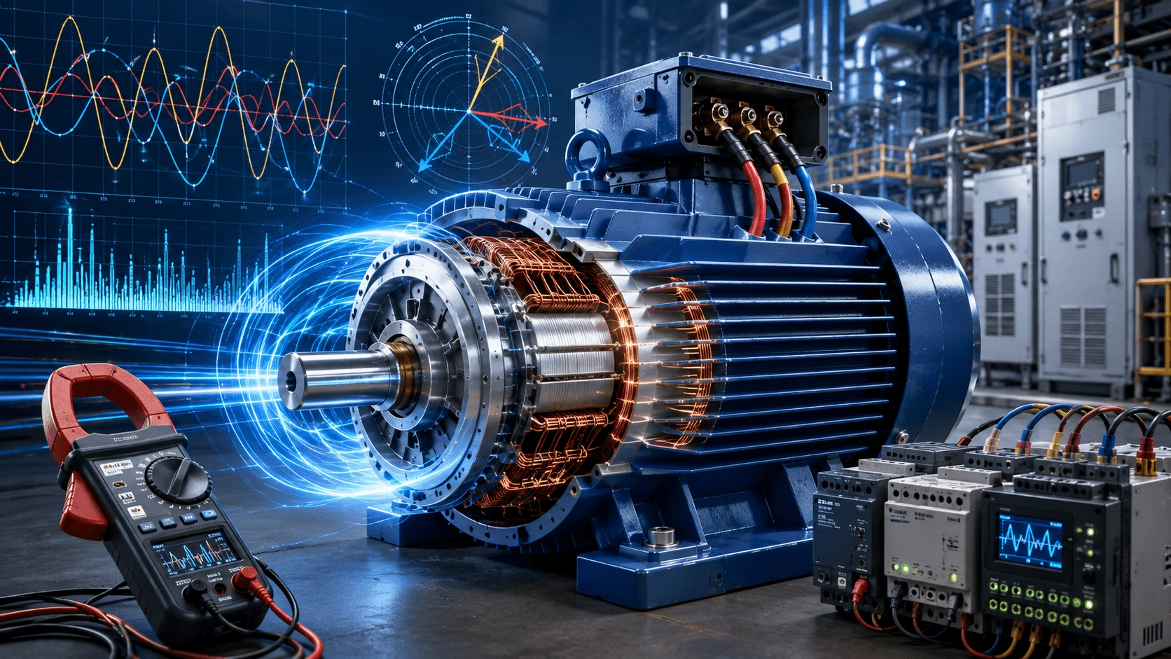
2026 AC Motor Current Engineering Guide: A comprehensive technical examination of Full-Load Current (FLC) calculations, starting inrush dynamics, harmonic distortion (THD) in VFD applications, advanced unbalance protection, thermal overload strategies, and the profound impacts of modern IE4/IE5 and PMSM technologies — compiled with TECHO industrial engineering expertise.
Introduction: Current as the Primary Diagnostic and Operational Variable
Electric current represents the fundamental flow variable in AC motor systems. It is the direct physical manifestation of electromagnetic torque production, thermal loading, real power consumption, and system stress. In the modern industrial landscape of 2026, where digital twins and AI-driven predictive maintenance are standard, motor current is no longer just a parameter for protection; it is the primary telemetry signal for condition monitoring, efficiency optimization, and process control.
Understanding motor current characteristics—from steady-state full-load operation through high-magnitude transient starting conditions and harmonic-rich inverter outputs—is non-negotiable for proper motor selection, protection coordination, and energy optimization. This guide provides a rigorous, engineering-grade analysis of AC motor current behavior, bridging the gap between theoretical electromagnetics and practical field application.
1. Full-Load Current (FLC) Analysis and Calculation
1.1 Fundamental Full-Load Current Equations
The full-load current (FLC) or full-load amps (FLA) represents the steady-state current drawn by a motor operating at its rated mechanical output power, voltage, speed, and frequency. For three-phase AC motors, the fundamental calculation incorporates both motor efficiency and power factor:
`I_FLC = (P_out × 1000) / (√3 × V_L-L × η × cosφ)`
Parameter Explanation:
- I_FLC = Full-Load Current (Amperes, A)
- P_out = Rated mechanical output power (kW)
- V_L-L = Line-to-line supply voltage (Volts, V)
- η = Motor full-load efficiency (expressed as a decimal, e.g., 0.95)
- cosφ = Motor full-load power factor (expressed as a decimal, e.g., 0.88)
For single-phase AC motors, the equation simplifies by removing the three-phase vector constant:
`I_FLC = (P_out × 1000) / (V × η × cosφ)`
1.2 NEC Table FLC vs. Nameplate FLA: A Critical Distinction
The National Electrical Code (NEC) and international IEC standards establish critical distinctions between code-derived FLC and manufacturer nameplate FLA values. Confusing these two is a root cause of protection coordination failures and failed electrical inspections.
| Metric | Source | Primary Engineering Application | Standard Reference |
|---|---|---|---|
| Table FLC | NEC Tables 430.248 / 430.250 (or IEC equivalent) | Sizing conductors, short-circuit breakers, and disconnects. | NEC 430.6(A)(1) |
| Nameplate FLA | Motor Manufacturer Nameplate | Sizing the specific thermal overload relay to protect the motor. | NEC 430.32 / IEC 60034-1 |
⚠️ Critical Engineering Rule:
Per NEC 430.6(A)(1), you must use the standard Ampere ratings from the NEC tables to determine wire sizes and branch-circuit short-circuit breakers. You do not use the motor's actual nameplate FLA for this purpose. However, for the separate overload relay (which protects the motor windings from slow overheating), you must use the exact nameplate FLA.
1.3 Practical Calculation Example
For a 50 HP (37.3 kW), 460V, three-phase motor with 95% efficiency and 0.88 power factor:
`I_FLC = (37.3 × 1000) / (√3 × 460 × 0.95 × 0.88)`
`I_FLC = 37,300 / 665.6 = 56.0 A`
Engineering Note: NEC Table 430.250 provides a standard FLC value of approximately 65A for a 50 HP, 460V motor. The discrepancy between the calculated value (56A) and the table value (65A) reflects the conservative assumptions in NEC tables, which are based on older, lower-efficiency motor designs to ensure universal safety margins.
2. Starting Current (Inrush Current) Analysis
2.1 Starting Current Characteristics
When an AC motor is energized at standstill, a massive inrush current occurs due to the absence of back-Electromotive Force (back-EMF) and the low impedance of the stationary rotor.
- First Half-Cycle Peak (Asymmetrical Inrush): Can exceed 20 to 30 times the normal FLC. This is a transient DC offset phenomenon (transformer magnetization + motor inrush) that decays within the first few cycles.
- Locked Rotor Current (LRA): After the DC offset decays, the current stabilizes at 6 to 8 times the FLC for standard NEMA Design B motors.
- Acceleration Period: As the rotor accelerates and back-EMF builds, the current decays smoothly from LRA down to FLC.
2.2 Locked Rotor Current (LRA) and Code Letters
NEMA establishes standardized locked rotor current ranges through code letters stamped on motor nameplates. These codes indicate the kVA per horsepower required at starting, dictating the necessary capacity of the electrical supply system.
| Code Letter | kVA/HP Range | Approximate LRA Multiplier | Typical Application Profile |
|---|---|---|---|
| A, B | 0 - 3.54 | 3.1× - 3.5× | High-efficiency, specialized designs |
| C, D | 3.55 - 4.0 | 4.0× - 4.5× | Low inrush requirements |
| G, H | 5.6 - 7.1 | 6.0× - 7.1× | Standard industrial motors (Most Common) |
| K, L | 8.0 - 9.0 | 8.0× - 9.0× | High starting torque designs |
| V | 12.5+ | 12.5×+ | Specialized high-inertia applications |
2.3 Starting Methods and Current Reduction
To mitigate severe voltage dips and mechanical shock, various starting methods are employed to reduce inrush current:
| Starting Method | Current (% of DOL) | Torque (% of DOL) | 2026 Application Context |
|---|---|---|---|
| Direct-On-Line (DOL) | 100% | 100% | Small motors (<10 HP) or robust grid systems. |
| Star-Delta (Y-Δ) | 33% | 33% | Medium motors with light starting loads (pumps/fans). |
| Autotransformer | 25% - 64% | 25% - 64% | Large motors; selectable taps for specific torque needs. |
| Soft Starter | 200% - 400% | Variable | Controlled acceleration; eliminates mechanical shock. |
| Variable Frequency Drive (VFD) | 100% - 150% | 100% - 150% | The 2026 Gold Standard. Full control, zero inrush. |
2.4 Voltage Dip and Thermal Stress (I²t)
Motor starting current causes a proportional voltage drop across the system impedance:
`V_motor = V_source - (I_start × Z_system)`
Furthermore, the thermal energy imparted to the rotor during acceleration is proportional to the square of the current multiplied by time (I²t). Frequent starts or prolonged acceleration times can melt rotor bars or degrade insulation. Modern motor protection relays utilize Thermal Memory algorithms to track this I²t accumulation, preventing the motor from restarting before it has adequately cooled.
3. Current, Load, and Efficiency Relationships
3.1 Part-Load Efficiency and Power Factor Dynamics
Motor efficiency and power factor vary significantly with load level. Current draw does not decrease linearly with load reduction because the magnetizing current (which creates the magnetic field) remains relatively constant regardless of the mechanical load.
- 100% Load: Peak or near-peak efficiency (94-97% for IE3/IE4 motors). Power factor is optimal.
- 75% Load: Often the absolute maximum efficiency point for modern premium motors. Current is roughly 75-80% of FLC.
- 50% Load: Efficiency drops slightly; power factor degrades significantly as the constant magnetizing current becomes a larger percentage of the total current. Current is roughly 55-65% of FLC.
- <25% Load (Severe Under-loading): Efficiency drops precipitously. The motor operates with a poor power factor, potentially incurring utility penalty charges.
3.2 Current-Based Load Estimation
For predictive maintenance, motor load can be estimated from current measurements, though this method has limitations at light loads due to power factor shifts:
`% Load ≈ (I_measured / I_FLC) × (V_measured / V_rated) × 100%`
For high-precision load estimation, especially for energy auditing, true input power measurement is required:
`% Load = (P_input_measured / P_input_rated) × 100%`
4. Current Harmonics and Power Quality
4.1 Harmonic Generation and Sequence Components
In 2026, with the ubiquitous presence of non-linear loads and VFDs, harmonic distortion is a primary concern. Harmonics are classified by their phase sequence rotation:
- Positive Sequence (1st, 4th, 7th): Rotates in the same direction as the fundamental. Adds to torque but increases copper heating.
- Negative Sequence (2nd, 5th, 8th, 11th): Rotates in the opposite direction. Creates a braking torque and induces severe, localized rotor heating. A mere 5% 5th harmonic voltage can increase motor losses by 10-15%.
- Zero Sequence (3rd, 6th, 9th): Does not flow in 3-wire systems but causes dangerous neutral overheating in 4-wire systems.
4.2 VFD-Generated Current Harmonics and SiC Technology
Traditional 6-pulse VFDs draw highly distorted, non-sinusoidal current, with Total Harmonic Distortion (THD_I) ranging from 30% to 50%.
2026 Technological Shift: The industry has largely transitioned to Active Front End (AFE) drives and Ultra-Low Harmonic (ULH) drives utilizing Silicon Carbide (SiC) semiconductors.
- SiC Inverters: Operate at switching frequencies > 20 kHz, effectively pushing harmonic energy into the ultrasonic range, reducing audible noise and lowering low-order THD_I to < 5%.
- Trade-off: While SiC drives reduce current harmonics, their extremely fast switching speeds (high dV/dt) generate high-frequency capacitive charging currents in long motor cables, which must be accounted for in drive sizing.
4.3 Harmonic Effects on Motor Health
- Skin and Proximity Effects: High-frequency harmonic currents are forced to the surface of the conductors, effectively reducing the cross-sectional area and increasing AC resistance (I²R losses).
- Stray Flux Losses: High-frequency flux components induce eddy currents in the motor frame, end bells, and bearings.
- Bearing Currents: Common-mode high-frequency currents induced by PWM drives can discharge through the motor bearings, causing Electrical Discharge Machining (EDM) pitting and premature mechanical failure. Mitigation: Shaft grounding rings and insulated bearings are now mandatory for VFD applications.
5. Advanced Current Monitoring and Protection Systems
5.1 Overload Protection and Thermal Modeling
Modern microprocessor-based motor protection relays (compliant with IEC 60255-149) do not just measure current; they calculate a real-time Thermal Image of the motor.
- Thermal Overload: Trips at 105-125% of FLA, utilizing a mathematical model that accounts for ambient temperature, starting time, and cooling time constants.
- Jam/Stall Protection: Trips rapidly (1-10 seconds) if current exceeds 150-300% of FLA, indicating a mechanical bind.
- Undercurrent Protection: Trips if current drops below 50-90% of FLA, detecting broken belts, dry pumps, or loss of load.
5.2 Current Imbalance and Phase Loss
Current imbalance is a silent killer of three-phase motors. It is calculated as:
`% Current Imbalance = [(Max(I_a, I_b, I_c) - Min(I_a, I_b, I_c)) / I_average] × 100%`
A voltage unbalance of just 2% can cause a current unbalance of 15-20%, leading to localized overheating that surface temperature sensors cannot detect. Protection relays must be set to trip at > 5-10% current unbalance. Single-phasing (loss of one phase) causes the remaining phases to draw 173% of normal current, requiring instantaneous protection.
5.3 Motor Current Signature Analysis (MCSA)
In 2026, MCSA is the cornerstone of predictive maintenance. By analyzing the frequency spectrum of the stator current, engineers can detect internal faults without opening the motor:
- Broken Rotor Bars: Identified by specific sideband frequencies around the fundamental line frequency (1 ± 2ks)f.
- Air Gap Eccentricity: Detected by distinct harmonic patterns indicating rotor-stator rubbing.
- Load Oscillations: Identifies mechanical misalignment or gearbox wear.
6. Special Current Considerations for Modern Motor Systems
6.1 IE3/IE4/IE5 High-Efficiency Motors
Modern premium efficiency motors achieve their ratings by reducing internal losses (thicker copper wires, better steel). Consequently, their Full-Load Current (FLA) is actually lower than older IE1/IE2 motors of the same horsepower.
Engineering Caution: When replacing an old motor with an IE4 motor, the nameplate FLA will be lower. If the overload relay is not reset to the new, lower nameplate FLA, the motor will be under-protected and may burn out under sustained overload.
6.2 Permanent Magnet Synchronous Motors (PMSM)
PMSMs exhibit fundamentally different current characteristics:
- Unity Power Factor: They draw almost zero reactive magnetizing current, resulting in a much lower total FLC compared to induction motors of the same kW rating.
- Demagnetization Risk: Under severe fault conditions (e.g., a sudden short circuit or extreme overcurrent), the strong armature reaction can permanently demagnetize the rotor magnets. PMSM drives must feature ultra-fast current limiting (often < 1 ms) to protect the magnets.
- High Fault Contribution: Unlike induction motors, where fault current decays rapidly, PMSMs can sustain high fault currents as long as the rotor is spinning, requiring specialized protective relaying.
7. Current Measurement Techniques and Instrumentation
7.1 True RMS vs. Average-Responding Meters
In a purely sinusoidal 50/60 Hz environment, average-responding clamp meters provide accurate readings. However, in modern plants with VFDs and non-linear loads, the current waveform is heavily distorted with a high crest factor.
- Average-responding meters can under-read distorted currents by 20-50%, leading to dangerous under-sizing of conductors.
- True RMS meters are strictly mandatory for all modern industrial current measurements.
7.2 Advanced Sensor Technologies
- Rogowski Coils: Flexible, air-core sensors that cannot saturate, making them ideal for measuring massive starting inrush currents and complex harmonic waveforms.
- Fluxgate Sensors: Provide ultra-high accuracy for DC and low-frequency AC current measurement, increasingly used in precision servo drives.
- Wireless IoT Sensors: Clamp-on sensors with integrated edge computing that transmit real-time current, THD, and power factor data directly to cloud-based digital twins via 5G/LoRaWAN.
8. System Design and Coordination
8.1 Feeder and Branch Circuit Sizing (NEC & IEC)
Proper conductor sizing ensures thermal stability and voltage regulation:
- Branch Circuit Conductors: Sized to 125% of the motor FLC (NEC 430.22).
- Feeder Conductors (Multiple Motors): 125% of the largest motor FLC + the sum of the FLCs of all other motors (NEC 430.24).
- Short-Circuit Protection: Sized per NEC 430.52 (typically 175-250% of FLC for inverse time breakers) to allow starting inrush without nuisance tripping, while still protecting the conductor.
8.2 Voltage Drop and Selective Coordination
Motor starting current causes significant voltage drop. Design criteria limit this to < 3% at full load and < 15% during starting to prevent contactor dropout and lighting flicker. Furthermore, protection devices must be selectively coordinated so that a fault on a specific motor branch trips only its local breaker, not the main facility feeder, ensuring maximum system uptime.
9. Future Trends in Motor Current Management
The management of motor current is rapidly evolving with the integration of advanced digital technologies:
- AI-Driven Edge Analytics: Smart motor controllers now feature onboard AI that continuously analyzes current waveforms to predict mechanical failures (e.g., bearing wear, cavitation in pumps) weeks before they occur.
- Wide Bandgap (SiC/GaN) Inverters: These semiconductors enable near-perfect sinusoidal current output, virtually eliminating harmonic heating and allowing for smaller, lighter motor designs.
- Integrated Motor-Drive Systems: The physical integration of the inverter directly onto the motor eliminates long cable runs, eradicating reflected wave voltage spikes and high-frequency capacitive ground currents.
- Digital Twin Commissioning: Virtual models of the motor and load are used to simulate starting current profiles and thermal limits in software before the physical system is ever energized.
10. Conclusion
AC motor current characteristics encompass a complex spectrum of phenomena, from steady-state full-load operation through high-magnitude transient starting currents, to harmonic-rich distorted waveforms in modern drive systems. Proper understanding of these current behaviors is essential for motor selection, protection coordination, system design, and energy optimization.
The critical distinctions between NEC table FLC and nameplate FLA, the management of 6-8× starting current multipliers, the mitigation of harmonic effects, and the implementation of sophisticated thermal and signature-based protection schemes represent core competencies for the modern electrical engineer. As motor technology evolves toward IE5 ultra-premium efficiency and integrated SiC drive systems, current analysis remains the fundamental diagnostic tool for ensuring reliable, efficient, and safe electromechanical operation.
Technical Summary
- Fundamental Current:
I_FLC = (P_out × 1000) / (√3 × V × η × cosφ)| NEC Table FLC is for wiring; Nameplate FLA is for overload protection. - Starting Dynamics: Locked Rotor Current (LRA) is typically 6-8× FLC | Inrush peak can reach 20-30× FLC for the first half-cycle.
- Power Quality: VFDs without AFE generate high THD (30-50%) | Negative sequence harmonics (5th, 11th) cause severe rotor heating.
- Protection Settings: Thermal Overload at 115-125% FLA | Phase Imbalance trip at > 5-10% | Ground fault at 30mA - 6A.
- System Design: Conductors sized at 125% FLC | Voltage drop must be < 3% at full load | True RMS measurement is mandatory.
- Modern Trends: PMSM motors draw significantly lower FLC but require ultra-fast fault protection | SiC drives and AI-driven MCSA are the 2026 industry standards.
Optimize Your Motor Current Systems with TECHO Expertise
Improper current management leads to nuisance tripping, catastrophic motor burnout, severe power quality penalties, and unplanned downtime. Our team of certified power quality and motor protection engineers specializes in advanced current analysis, harmonic mitigation, and predictive maintenance integration.
From sizing complex multi-motor feeders and configuring AI-driven protection relays to implementing Active Front End (AFE) drives for harmonic elimination, we deliver precision-engineered solutions tailored to your facility's unique electrical architecture.
Request Your Custom AC Motor Current and Power Quality Consultation to ensure your drive systems operate with maximum efficiency, safety, and reliability.
© 2026 TECHO Industrial Engineering Solutions. All rights reserved. This document is intended for professional engineering reference. All motor selections, conductor sizing, and protection coordination must be validated by a qualified Professional Engineer (PE) or Chartered Engineer (CEng) in strict accordance with local electrical codes (NEC/IEC), IEEE standards, and site-specific safety regulations.