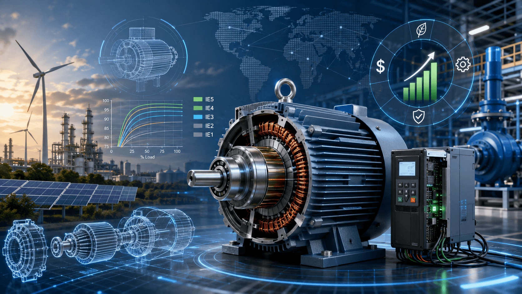
2026 AC Motor Efficiency Engineering Guide: A comprehensive technical examination of International Efficiency (IE1–IE5) classifications, fundamental loss mechanisms, advanced motor topologies (PMSM/SynRM vs. Induction), Variable Frequency Drive (VFD) system integration, and holistic optimization strategies — compiled with TECHO industrial engineering expertise.
Introduction: The Strategic Imperative of Motor Efficiency
Electric motor efficiency represents one of the most critical performance metrics in modern industrial and commercial infrastructure. According to the International Energy Agency (IEA), electric motor systems consume approximately 45% to 50% of global electricity production. Consequently, even marginal improvements in electromechanical energy conversion translate to massive reductions in global carbon emissions and substantial operational cost savings.
In the context of 2026's stringent global decarbonization targets and corporate ESG (Environmental, Social, and Governance) mandates, motor efficiency is no longer merely a technical specification; it is a strategic operational imperative. This guide provides a rigorous, engineering-grade analysis of AC motor efficiency, bridging the gap between electromagnetic theory, international regulatory standards, and practical system-level optimization.
1. Fundamental Principles and Global Significance
The efficiency (\eta) of an electric motor is fundamentally defined as the ratio of useful mechanical output power to the total electrical input power. The mathematical representation is:
`η = (P_out / P_in) × 100% = [P_out / (P_out + Σ Losses)] × 100%`
Parameter Explanation:
- P_out: Mechanical power delivered to the driven load (kW).
- P_in: Total electrical power drawn from the supply (kW).
- Σ Losses: The summation of all internal energy dissipation mechanisms (copper, iron, mechanical, and stray losses).
The pursuit of higher efficiency is essentially the engineering challenge of minimizing \Sigma Losses. As global energy costs rise and carbon pricing mechanisms (such as the EU Emissions Trading System) become more prevalent, the financial penalty for inefficiency has never been higher.
2. International Efficiency Classification Standards (IEC 60034-30)
The International Electrotechnical Commission (IEC) established the IEC 60034-30 standard to harmonize global motor efficiency classifications, eliminating regional discrepancies and facilitating international trade. This system defines International Efficiency (IE) classes ranging from IE1 through IE5.
| IE Class | Designation | Efficiency Range (4-pole, 50Hz) | Primary Technological Characteristics |
|---|---|---|---|
| IE1 | Standard Efficiency | 87% - 91% | Basic efficiency, legacy designs, minimal material optimization. |
| IE2 | High Efficiency | 91% - 94% | Improved magnetic materials, moderate energy savings. |
| IE3 | Premium Efficiency | 94% - 96% | Advanced lamination steel, optimized windings, significantly reduced losses. |
| IE4 | Super Premium | 96% - 97% | Superior materials, precision manufacturing, advanced thermal management. |
| IE5 | Ultra-Premium | > 97% | Emerging technology, 20% lower losses than IE4, cutting-edge design. |
2.1 Global Regulatory Landscape
Regulatory frameworks are aggressively driving the adoption of higher IE classes:
- European Union: The Ecodesign Regulation (EU) 2019/1781 mandates IE3 for most three-phase motors (0.75-1000 kW) and requires IE4 for motors between 75-200 kW.
- North America: The US Department of Energy (DOE) and Natural Resources Canada align closely with NEMA Premium (equivalent to IE3), with ongoing rulemakings pushing toward IE4 equivalents.
- Asia: China’s GB 18613-2020 standard mandates IE3 as the minimum efficiency limit value (MEV) for low-voltage three-phase induction motors, effectively phasing out IE2.
2.2 Technical Implementation for Higher Efficiency Classes
Achieving elevated IE classifications requires systematic design optimization across multiple engineering domains:
- Enhanced Stator Designs: Increased copper mass in windings reduces resistive losses. Optimized slot geometries and automated insertion techniques improve copper fill factors to 75-80%.
- Advanced Magnetic Materials: Utilization of higher-grade, ultra-thin silicon steel laminations (0.35 mm or thinner) minimizes eddy current and hysteresis losses.
- Optimized Air Gap Geometry: Precision machining maintains air gap uniformity within ±5%, reducing magnetic circuit reluctance and stray load losses.
- Copper Rotor Technology: Replacing traditional aluminum die-cast rotors with copper reduces rotor I²R losses by 15-25% due to copper's superior electrical conductivity.
3. Comprehensive Loss Mechanisms Analysis
To optimize efficiency, engineers must systematically categorize and mitigate the five principal loss mechanisms within an AC motor.
3.1 Ohmic (Copper) Losses (P_{Cu})
These resistive losses occur in both stator and rotor windings according to Joule's law of heating. They vary with the square of the load current and represent the dominant loss component at full load (typically 35-40% of total losses).
`P_Cu = I² × R = (P_out² × R) / (V² × η² × cos²φ)`
Mitigation: Increasing conductor cross-sectional area (using more copper) and ensuring optimal operating temperatures to prevent resistance escalation.
3.2 Core (Iron) Losses (P_{Fe})
Magnetic losses in the stator and rotor cores comprise two distinct physical phenomena:
Hysteresis Losses (P_h): Energy dissipated during the cyclic magnetization and demagnetization of the core material. Governed by the Steinmetz equation:
`P_h = k_h × f × B_max^n`
(Where k_h is the hysteresis coefficient, f is frequency, B_{max} is maximum flux density, and n is the Steinmetz exponent, typically 1.6 to 2.0).
Eddy Current Losses (P_e): Circulating currents induced within the core laminations by changing magnetic fields.
`P_e = k_e × (f × B_max × t)²`
(Where t represents lamination thickness and k_e is the eddy current coefficient).
Mitigation: Utilizing ultra-thin electrical steel (0.35 mm or 0.27 mm), high silicon content steel to increase electrical resistivity, and applying advanced inter-lamination insulation coatings.
3.3 Mechanical Losses (P_{mech})
Friction and windage losses result from bearing friction, air resistance against rotating components, and the power consumed by the external cooling fan.
`P_mech = P_bearing + P_windage + P_fan`
Mitigation: Employing low-friction hybrid ceramic bearings, optimizing the aerodynamic profile of the cooling fan using Computational Fluid Dynamics (CFD), and utilizing independent forced cooling (IC416) to eliminate shaft-mounted fan losses at variable speeds.
3.4 Stray Load Losses (P_{stray})
These encompass residual losses not captured by the primary categories, including harmonic losses from non-sinusoidal flux distributions, high-frequency skin effect losses in conductors, and leakage flux losses in end windings. Stray losses are particularly exacerbated in inverter-fed motors due to the high-frequency harmonic content of PWM voltage waveforms.
3.5 Standardized Efficiency Calculation
IEEE 112 Method B (and IEC 60034-2-1) provides the standardized approach for efficiency determination, calculating total efficiency as:
`η = [P_out / (P_out + P_Cu + P_Fe + P_mech + P_stray)] × 100%`
These standards mandate rigorous test protocols, including the segregation of individual loss components, to ensure accurate and repeatable efficiency ratings.
4. Comparative Motor Technology Analysis
The choice of motor topology fundamentally dictates the efficiency profile, partial-load performance, and total cost of ownership.
4.1 Induction Motors (ACIM)
AC induction motors operate on the principle of electromagnetic induction. The fundamental characteristic is slip (s)—the difference between synchronous speed and actual rotor speed:
`s = (n_s - n_r) / n_s = (f_s - f_r) / f_s`
Slip-related losses fundamentally limit maximum achievable efficiency. Furthermore, induction motors exhibit significant efficiency and power factor degradation under partial load conditions (dropping 12-18% below 50% loading), making precise right-sizing critical.
4.2 Permanent Magnet Synchronous Motors (PMSM)
PMSMs utilize rare-earth permanent magnets (typically NdFeB) to establish the rotor magnetic field, entirely eliminating rotor resistive losses.
- Efficiency Advantage: Achieves 25-30% reduction in total losses compared to induction motors.
- Partial-Load Performance: Maintains >94% efficiency across a broad 10-150% load range.
- Power Density: Superior magnetic field strength enables smaller frame sizes, reducing windage and mechanical losses.
- Limitation: Requires mandatory VFD integration and carries risks of irreversible demagnetization under extreme thermal or overcurrent conditions.
4.3 Synchronous Reluctance Motors (SynRM)
SynRMs achieve IE4/IE5 efficiency levels without relying on rare-earth materials. Torque is produced through the rotor's tendency to align with the minimum reluctance path of the stator magnetic field. Modern ferrite-assisted SynRMs bridge the performance gap between pure reluctance and PMSM topologies, offering a highly sustainable, cost-effective alternative for variable-speed applications.
4.4 Comparative Efficiency Performance Matrix
| Parameter | Induction Motor (IE3) | PMSM (IE5) | SynRM (IE4/IE5) |
|---|---|---|---|
| Peak Efficiency | 94% - 96% | 96% - 98% | 95% - 97% |
| 50% Load Efficiency | 88% - 92% | 94% - 96% | 93% - 95% |
| Power Factor | 0.80 - 0.90 | 0.95 - 0.99 | 0.70 - 0.85 |
| VFD Requirement | Optional | Mandatory | Mandatory |
| Material Dependency | Low (Copper/Steel) | High (Rare-earth) | Low (Steel/Ferrite) |
5. Variable Frequency Drive (VFD) Integration and System Efficiency
Modern efficiency optimization extends beyond the motor nameplate to encompass the complete electromechanical system. The combined system efficiency is calculated as:
`η_system = η_motor × η_drive × η_transmission`
5.1 The Affinity Laws and Energy Savings
For variable torque applications (centrifugal pumps and fans), integrating a VFD allows the motor speed to be matched precisely to the process demand. According to the Affinity Laws, power consumption is proportional to the cube of the speed. Reducing the motor speed by just 20% results in an energy consumption reduction of approximately 50%, yielding massive operational savings that far outweigh the drive's internal losses (typically 2-4%).
5.2 Advanced Drive Technologies
Modern VFDs utilize advanced power electronics to maximize system efficiency:
- Silicon Carbide (SiC) and Gallium Nitride (GaN): Wide bandgap semiconductors enable switching frequencies >20 kHz with minimal switching losses, achieving drive efficiencies >98% and significantly reducing motor harmonic heating.
- Active Front End (AFE): AFE drives provide near-unity power factor and ultra-low harmonic distortion (THD < 5%) on the input side, eliminating grid penalties and reducing facility-wide distribution losses.
6. High Voltage Motor Efficiency Considerations
IEC 60034-30-3 extends efficiency classification to high voltage AC motors (1-11 kV, 200-2000 kW). High-voltage designs introduce unique challenges, including complex insulation systems, increased leakage flux, and specialized cooling requirements.
The nominal efficiency calculation for high voltage motors incorporates specific correction factors:
`η_n = c_u × c_c × [1 / (1 + c_s × (1/η_r - 1))]`
Parameter Explanation:
- c_u: Voltage level correction factor.
- c_c: Cooling method correction factor (e.g., IC411, IC511, IC81W).
- c_s: Starting condition correction factor.
- η_r: Reference efficiency.
These corrections ensure that medium-voltage motor efficiency classifications accurately reflect the specific technical constraints and auxiliary power requirements of high-voltage applications.
7. Comprehensive Efficiency Optimization Strategies
Achieving optimal efficiency requires a holistic approach spanning design, operation, and maintenance.
7.1 Design Phase Optimization
- Electromagnetic FEA: Utilizing Finite Element Analysis to optimize magnetic flux paths, minimize saturation, and reduce stray losses.
- Thermal Management: Implementing advanced cooling channel designs and vacuum pressure impregnation (VPI) for windings to ensure optimal heat transfer and insulation longevity.
7.2 Operational Optimization
- Right-Sizing: Eliminating the historical practice of oversizing motors by 20-30%. Motors should operate ideally between 75% and 100% of rated load to maximize both efficiency and power factor.
- Power Quality Management: Maintaining voltage unbalance below 1% and Total Harmonic Distortion (THD) below 5% to prevent auxiliary losses and localized overheating.
7.3 Predictive Health Condition Monitoring
Motor efficiency degrades progressively with developing faults. Anomaly power losses from bearing degradation, rotor bar cracking, or stator winding deterioration can reduce efficiency by 5-15% before catastrophic failure.
- IIoT Integration: Deploying smart sensors for continuous vibration analysis, thermal imaging, and Motor Current Signature Analysis (MCSA).
- Digital Twins: Utilizing real-time digital replicas of the motor to predict efficiency degradation and schedule maintenance precisely when needed, preserving rated efficiency throughout the operational life.
8. Economic Analysis and Environmental Impact
The transition to premium efficiency motors is driven by compelling Total Cost of Ownership (TCO) economics. The initial purchase price of a motor represents less than 3% of its lifecycle cost; energy consumption accounts for over 90%.
8.1 Lifecycle Cost (LCC) and Payback Analysis
The Life Cycle Cost is calculated as:
`LCC = Initial Cost + (Annual Energy Cost × Operational Life) + Maintenance Cost - Salvage Value`
Economic Comparison (75 kW Motor, 6,000 Hours/Year, €0.12/kWh):
| Efficiency Class | Assumed Efficiency | Annual Energy Cost | Annual Savings vs IE1 | Estimated Simple Payback |
|---|---|---|---|---|
| IE1 | 90.0% | €6,000 | Baseline | N/A |
| IE2 | 93.0% | €5,806 | €194 | 2.5 Years |
| IE3 | 95.0% | €5,684 | €316 | 1.8 Years |
| IE4 | 96.5% | €5,596 | €404 | 1.4 Years |
| IE5 | 97.5% | €5,538 | €462 | 1.2 Years |
8.2 Environmental Impact
A 1% efficiency improvement across the global installed base of electric motors would reduce global CO₂ emissions by approximately 100 million tons annually. Upgrading to IE4/IE5 motors is one of the most cost-effective and rapidly deployable decarbonization strategies available to heavy industry.
9. Future Trends and Emerging Technologies
The pursuit of IE5 and beyond is driving rapid innovation across multiple disciplines:
- Advanced Magnetic Materials: The development of amorphous metal cores, which exhibit 70% lower hysteresis losses compared to conventional grain-oriented silicon steel.
- Integrated Motor-Drive Systems: The physical integration of the inverter directly onto the motor terminal box, eliminating cable losses, mitigating dV/dt reflected wave issues, and optimizing thermal management.
- Sustainable Material Alternatives: The commercialization of ferrite-assisted synchronous reluctance motors, which achieve IE4+ performance while eliminating the geopolitical and environmental risks associated with rare-earth mining.
- AI-Driven Efficiency Optimization: Machine learning algorithms embedded within VFDs that continuously analyze load profiles and autonomously adjust motor flux levels to minimize losses in real-time.
10. Conclusion
AC motor efficiency represents a multidimensional engineering challenge encompassing electromagnetic design, advanced material science, precision thermal management, and holistic system integration. The evolution from IE1 to IE4/IE5 classifications reflects decades of rigorous incremental improvements, pushing electromechanical conversion ever closer to theoretical physical limits.
While induction motors remain the workhorse for general-purpose applications due to their inherent robustness, Permanent Magnet Synchronous Motors (PMSM) and Synchronous Reluctance Motors (SynRM) are rapidly capturing market share in variable-speed applications, offering superior partial-load efficiency and system-level energy savings.
Regulatory frameworks globally mandate continued efficiency improvements, driven by both economic imperatives and environmental sustainability goals. Engineers and facility managers must look beyond initial purchase price and nameplate efficiency, considering partial-load performance, VFD integration, power quality, and total lifecycle costs. As the industry advances toward IE5 standards, the convergence of digitalization, advanced materials, and system-level optimization will define the next generation of ultra-efficient, sustainable electric drive systems.
Technical Summary
- Fundamental Efficiency:
`η = [P_out / (P_out + Σ Losses)] × 100%`| Losses comprise Copper, Iron, Mechanical, and Stray components. - IE Classifications: IE3 (94-96%) | IE4 (96-97%) | IE5 (>97%).
- Technology Comparison: PMSM offers the highest peak and partial-load efficiency but requires VFDs; SynRM offers IE4/IE5 efficiency without rare-earth dependencies; Induction motors remain robust but suffer at partial loads.
- System Integration: VFD integration enables 20-50% energy savings in variable torque applications via the Affinity Laws. System efficiency
`η_system = η_motor × η_drive × η_transmission`. - Optimization Strategy: Right-sizing motors, ensuring high power quality (<1% unbalance, <5% THD), and deploying IIoT-based predictive maintenance are critical for sustaining peak efficiency over the asset's lifecycle.
- Economic Impact: Premium efficiency motors (IE3/IE4) typically achieve a simple payback period of 1 to 2 years, delivering massive reductions in Total Cost of Ownership (TCO) and Scope 2 carbon emissions.
Optimize Your Motor Systems with TECHO Engineering Expertise
Navigating the complexities of motor efficiency, from IE class selection to VFD system integration and predictive maintenance, requires specialized engineering expertise. Suboptimal motor systems result in inflated energy costs, excessive carbon footprints, and premature asset degradation.
Our team of certified electrical and mechanical engineers specializes in comprehensive energy audits, advanced motor system design, and lifecycle cost optimization. We partner with industrial and commercial facilities to design bespoke, high-efficiency drive solutions that align with your operational goals and sustainability mandates.
Request Your Custom AC Motor Efficiency and System Optimization Consultation to unlock significant energy savings and ensure your electromechanical assets operate at the pinnacle of modern engineering standards.
© 2026 TECHO Industrial Engineering Solutions. All rights reserved. This document is provided for advanced technical reference. All motor selections, efficiency calculations, and system designs must be validated by a qualified Professional Engineer (PE) or Chartered Engineer (CEng) in strict accordance with IEC 60034, IEEE 112, and applicable local energy codes.