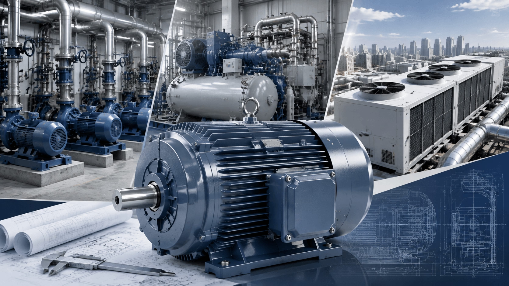
A comprehensive engineering guide to selecting three-phase motors for pumps, compressors, and HVAC systems—covering torque-speed profiles, sizing methodology, efficiency classification, VFD integration, and 2026 regulatory standards. Expert technical guidance from Techo Electrical & Mechanical (Titecho).
1. Introduction
Selecting a three-phase motor for fluid-handling and air-moving applications represents one of the most common yet technically nuanced decisions facing mechanical and electrical engineers. A pump, compressor, or HVAC fan constitutes a system-level design challenge where the motor must match not only the steady-state power requirement but also the torque-speed characteristics, starting dynamics, thermal constraints, and efficiency profile of the driven load.
An undersized motor risks thermal failure and premature winding degradation; an oversized motor wastes energy, reduces power factor, and may operate below its efficiency sweet spot. This guide provides a systematic, application-focused methodology for motor selection across these three critical domains.
2. Understanding Load Characteristics: The Foundation of Selection
2.1 Torque-Speed Profiles by Application Type
The first step in motor selection is characterising the load torque-speed relationship, as this determines the motor's torque requirements across the entire operating envelope:
| Load Type | Torque Relationship | Typical Applications | Motor Implications |
|---|---|---|---|
| Variable Torque (Quadratic) | T ∝ N², P ∝ N³ | Centrifugal pumps, axial fans, centrifugal compressors | Lower starting torque; VFDs yield dramatic energy savings |
| Constant Torque | T = constant, P ∝ N | Positive displacement pumps, reciprocating compressors, screw compressors, conveyors | High starting torque required; constant V/Hz ratio with VFD |
| Constant Power | P = constant, T ∝ 1/N | Machine tools, winding equipment | Field weakening needed above base speed |
Centrifugal pumps exemplify the quadratic torque law: at 50% speed, torque drops to 25% and power to 12.5% of rated values. This is precisely why VFD-controlled pump systems can achieve 50–70% energy reduction at part-load conditions.
2.2 Duty Cycle Classification (IEC 60034-1)
Motor thermal sizing depends fundamentally on the duty cycle. IEC 60034-1 defines ten duty types (S1–S10):
| Duty Type | Description | Typical Application |
|---|---|---|
| S1 (Continuous) | Constant load until thermal equilibrium | Base-load pumps, HVAC chillers, air compressors |
| S2 (Short-time) | Limited duration (10, 30, 60, 90 min) followed by rest | Emergency pumps, fire suppression systems |
| S3 (Intermittent periodic) | Repeated cycles with constant load; starts/hour critical | Crane hoists, elevator compressors |
| S4–S6 | Varying cyclic loads with starting/braking effects | Elevator pumps, hydraulic power packs |
| S7–S10 | Discrete loads, electric braking, non-periodic | Test stands, special machinery |
For pump and HVAC applications, S1 continuous duty is the default assumption. Compressors may operate under S1 or S3 depending on demand profile and receiver tank sizing.
3. Power and Speed Sizing
3.1 Mechanical Power Calculation
The fundamental sizing equation relates torque, speed, and power:
P_mech = (T × N) / 9550
Where:
- P_mech = Mechanical power (kW)
- T = Torque (N·m)
- N = Rotational speed (rpm)
For pumps, brake horsepower (BHP) is determined from the pump curve at the operating point—the intersection of the pump performance curve and the system curve:
BHP = (Q × H × SG) / (3960 × η_pump) (US customary units)
P_kW = (Q × H × ρ × g) / (3600 × η_pump) (Metric units)
Where:
- Q = Flow rate (GPM or m³/h)
- H = Total dynamic head (ft or m)
- SG = Specific gravity (dimensionless)
- ρ = Fluid density (kg/m³)
- g = Gravitational acceleration (9.81 m/s²)
- η_pump = Pump efficiency (decimal)
3.2 Motor Sizing Margin and Non-Overloading Requirement
A critical rule in pump motor selection: the motor must be non-overloading to the end of the pump curve. This means:
P_motor ≥ P_pump,max / η_transmission
Where:
- P_pump,max = Power at maximum flow (run-out condition)
- η_transmission = Transmission efficiency (typically 0.95–1.0 for direct coupling)
For centrifugal pumps, power increases continuously toward the run-out point; for axial-flow pumps, power peaks at shut-off head.
Recommended Service Factors:
| Application | Service Factor |
|---|---|
| Centrifugal pumps | 1.10–1.15 |
| Positive displacement pumps | 1.15–1.25 (torque spikes) |
| Reciprocating compressors | 1.20–1.30 (pulsating torque) |
| HVAC fans | 1.10–1.15 |
3.3 Speed Selection and Pole Count
Standard motor synchronous speeds at 50/60 Hz:
| Poles | 50 Hz (rpm) | 60 Hz (rpm) | Application Guidance |
|---|---|---|---|
| 2 | 3000 | 3600 | High-head, low-flow pumps; high-pressure compressors |
| 4 | 1500 | 1800 | Most common; balanced performance for pumps, fans, compressors |
| 6 | 1000 | 1200 | High-flow, low-head pumps; large HVAC fans; reduced NPSH requirements |
| 8 | 750 | 900 | Very large flow applications; low-speed positive displacement pumps |
Engineering Trade-off: Lower-speed motors (6-pole, 8-pole) reduce NPSH requirements, wear rates, and acoustic noise but require larger frames for equivalent power. Higher-speed motors (2-pole) offer compactness but increase cavitation risk and bearing loads.
4. Torque Verification: The Critical Overlay
4.1 Pump Torque-Speed Curves
For centrifugal pumps, the torque-speed relationship follows:
T_pump = T_rated × (N / N_rated)²
However, at zero speed, static friction and inertia require approximately 15–20% of full-load torque to initiate rotation. The motor must provide accelerating torque—the margin between motor torque and pump torque—throughout the entire speed range:
T_accel = T_motor − T_pump > 0 (for all N from 0 to N_rated)
4.2 Starting Method Impact on Torque Availability
| Starting Method | Voltage at Motor | Starting Torque (% FLT) | Application Suitability |
|---|---|---|---|
| Direct-On-Line (DOL) | 100% | 150–250% | Small pumps (< 10 kW), robust grid |
| Star-Delta (Y-Δ) | 58% | 33–50% | Light-start pumps; NOT for high-inertia loads |
| Soft Starter (SCR) | 30–80% (ramp) | 30–150% | Medium pumps; controlled acceleration |
| VFD | Variable | 100–150% | All variable-speed applications; best energy savings |
Critical consideration for pumps: Starting with the discharge valve closed reduces centrifugal pump torque to 50–60% of full-load torque at full speed, easing acceleration. For axial-flow pumps, closed-valve starting is dangerous—torque can exceed 150% of full-load torque at shut-off. Always obtain the pump manufacturer's torque-speed curves for both open-valve and closed-valve conditions.
4.3 Inertia and Acceleration Time
The acceleration time must be short enough to prevent thermal damage to the motor windings:
t_accel = 2π × (J_motor + J_load) × ΔN / (60 × T_avg,accel)
Where:
- J = Moment of inertia (kg·m²)
- ΔN = Speed change (rpm)
- T_avg,accel = Average accelerating torque (N·m)
Motor manufacturers specify a maximum inertia (WK² or GD²) for each starting method. Exceeding this limit causes excessive heating—particularly critical for high-inertia pumps with large impellers or flywheels.
5. Efficiency Class Selection: The 2026 Regulatory Context
5.1 Minimum Efficiency Requirements
As of 2026, global regulations mandate minimum efficiency levels:
| Jurisdiction | Power Range | Minimum Efficiency | Effective Date |
|---|---|---|---|
| European Union | 0.75–1000 kW | IE3 (Premium) | July 2021 |
| European Union | 75–200 kW | IE4 (Super Premium) | July 2023 |
| United States | General purpose | NEMA Premium (~IE3) | EISA 2007 |
| United States | 1–500 hp | DOE IE4 equivalent | June 2027 |
| China | Various | GB 18613 IE3 | 2016 onward |
5.2 Application-Specific Efficiency Guidance
| Application | Recommended IE Class | Rationale |
|---|---|---|
| Continuous-duty pumps (water, wastewater) | IE4 or IE5 | Long operating hours; energy dominates TCO |
| Intermittent pumps (sump, stormwater) | IE3 | Lower utilisation reduces energy savings payback |
| Base-load HVAC chillers | IE4 | 24/7 operation; part-load efficiency critical |
| Cycling HVAC fans | IE3 with VFD | VFD savings exceed motor efficiency gains |
| Air compressors (industrial) | IE4 | High duty cycle; compressed air is expensive energy |
| Refrigeration compressors | IE4 or IE5 | Thermal efficiency directly affects COP |
Key Insight: For variable-torque applications with VFDs, part-load efficiency often matters more than full-load efficiency. Permanent magnet synchronous motors (PMSM) and synchronous reluctance motors (SynRM) maintain 94–96% efficiency at 50% load, versus 88–92% for standard induction motors.
6. Environmental and Mechanical Specifications
6.1 Enclosure and Protection
| Application Environment | Recommended IP Rating | Cooling Method | Notes |
|---|---|---|---|
| Clean indoor HVAC | IP44–IP55 | TEFC (IC411) | Standard for commercial buildings |
| Outdoor/pump stations | IP55–IP65 | TEFC with sunshield | Prevent water ingress |
| Washdown (food/pharma) | IP66–IP69K | Stainless steel frame | Hygienic design |
| Hazardous (oil/gas) | Ex d, Ex e (ATEX/IECEx) | TEFC or pressurised | Certification mandatory |
| Submersible pumps | IP68 | Water-filled or oil-filled | Dedicated submersible motors |
6.2 Thermal Derating Factors
Motors must be derated for non-standard conditions per IEC 60034-1:
| Condition | Standard Limit | Derating Required If | Typical Derating |
|---|---|---|---|
| Ambient temperature | 40°C | > 40°C | 1% per °C above 40°C |
| Altitude | ≤ 1000 m | > 1000 m | 1% per 100 m above 1000 m |
| Voltage imbalance | < 1% | > 1% | Significant; investigate cause |
| Frequency variation | ±5% | > ±5% | Consult manufacturer |
Voltage imbalance is particularly destructive in HVAC applications: a 3.5% voltage imbalance can increase winding temperatures by 25°C, reducing insulation life by 50%.
7. VFD Compatibility and Integration
7.1 When VFDs Are Essential
VFDs are no longer optional for many pump, compressor, and HVAC applications:
| Application | VFD Benefit | Energy Savings |
|---|---|---|
| Variable-flow pumps | Match pump speed to system demand | 30–50% |
| HVAC fan systems | Part-load operation (AHUs, cooling towers) | 20–40% |
| Compressor capacity control | Eliminate load/unload cycling | 15–25% |
| Soft starting | Eliminate inrush current and water hammer | Indirect (infrastructure cost) |
7.2 Inverter-Duty Motor Requirements
Standard motors operated on VFDs require these enhancements:
| Feature | Standard Motor | Inverter-Duty Motor |
|---|---|---|
| Insulation class | Class F (155°C) | Class F or H with reinforced turn insulation |
| Voltage withstand | 1600 V peak | 2000–3000 V peak (for long cable runs) |
| Bearing protection | None | Insulated bearings or shaft grounding ring |
| Cooling | Shaft-mounted fan | Independent cooling fan (IC416) for low-speed operation |
| Speed range | Limited (typically 2:1) | 10:1 or 100:1 constant torque; 4:1 variable torque |
Bearing Current Mitigation:
PWM inverters induce shaft voltages through capacitive coupling. Without protection, EDM (electrical discharge machining) pitting destroys bearings within months. Solutions include:
- Ceramic hybrid bearings (Si₃N₄ balls)
- Insulated bearing housings (Al₂O₃ coating)
- Shaft grounding rings (carbon fibre brushes)
8. Application-Specific Selection Guidelines
8.1 Centrifugal Pumps
Selection Workflow:
- Determine system curve: Calculate TDH = static head + friction head + pressure head
- Select pump: Find operating point at intersection of pump curve and system curve; verify near BEP
- Check NPSH: Ensure NPSH_available > NPSH_required + 0.5–1.0 m margin at all operating points
- Size motor non-overloading: Rated power ≥ BHP at run-out / transmission efficiency
- Verify torque: Overlay pump and motor torque-speed curves; ensure positive accelerating margin
- Select starting method: Closed-valve start for centrifugal; open-valve start for axial-flow
Special Cases:
- High-specific-speed pumps (mixed/axial flow): Torque may increase toward shut-off; size motor for worst case
- Viscous fluids: Viscosity > 300 cSt requires PD pump, not centrifugal
8.2 Compressors
| Compressor Type | Torque Characteristic | Motor Selection Notes |
|---|---|---|
| Reciprocating | Pulsating torque; high starting torque | High service factor (1.25–1.35); flywheel for smoothing |
| Rotary screw | Constant torque; smooth | Standard starting; VFD for capacity control |
| Centrifugal | Quadratic (similar to pump) | Non-overloading to surge point; anti-surge control |
| Scroll | Constant torque; moderate starting | Standard selection; VFD for modulation |
Critical for reciprocating compressors: The pulsating torque creates torsional vibrations. Motor–compressor coupling selection (disc, grid, or elastomeric) must account for the torsional critical speed to avoid resonance.
8.3 HVAC Systems
| HVAC Component | Load Type | Motor Considerations |
|---|---|---|
| Centrifugal chillers | Variable torque | High-efficiency (IE4); VFD for part-load optimisation |
| Cooling tower fans | Variable torque | Large diameter, low speed; often 6-pole or 8-pole |
| AHU supply/return fans | Variable torque | VFD mandatory for energy code compliance |
| Refrigeration compressors | Constant torque | Hermetic or semi-hermetic; motor integrated |
| Exhaust fans | Variable torque | Corrosion-resistant coatings; spark-resistant construction |
Energy Code Compliance: ASHRAE 90.1 and IECC mandate VFDs on fans > 0.75 kW and pumps > 1.5 kW. Motor efficiency must meet or exceed NEMA Premium (IE3 equivalent).
9. Total Cost of Ownership (TCO) Analysis
A rigorous TCO model informs motor selection beyond first cost:
TCO = C_purchase + C_installation + Σ [ (C_energy,t + C_maintenance,t) / (1 + r)^t ] + C_downtime + C_disposal
Where:
- C = Cost component
- t = Year index (1 to N)
- r = Discount rate (decimal)
- N = Expected service life (years)
Example: 75 kW centrifugal pump motor, 6,000 hrs/year, 15-year life:
| Cost Component | IE3 Motor | IE4 Motor | IE4 + VFD |
|---|---|---|---|
| Purchase + installation | $8,000 | $10,500 | $14,000 |
| Annual energy cost | $45,000 | $42,750 | $31,500 |
| 15-year energy cost | $675,000 | $641,250 | $472,500 |
| Maintenance (15 yr) | $12,000 | $10,500 | $15,000 |
| Total 15-year TCO | $695,000 | $662,250 | $501,500 |
Conclusion: The VFD investment delivers the highest return, even with a premium motor. For constant-speed applications, IE4 pays back in 12–24 months.
10. Common Selection Errors and How to Avoid Them
| Error | Consequence | Prevention |
|---|---|---|
| Oversizing "just to be safe" | Low power factor, reduced efficiency, higher cost | Size to actual load with 10–15% margin |
| Ignoring pump run-out power | Motor overload at high flow | Non-overloading selection to end of curve |
| Specifying standard motor for VFD | Premature insulation failure, bearing fluting | Specify inverter-duty with reinforced insulation |
| Neglecting NPSH margin | Cavitation, impeller damage, vibration | NPSH_available ≥ NPSH_required + 0.5 m minimum |
| Wrong duty cycle assumption | Thermal failure in intermittent service | Verify S1–S10 classification matches application |
| Voltage imbalance ignored | Uneven current, overheating, shortened life | Measure phase-to-phase; keep < 1% |
11. Conclusion
Selecting the right three-phase motor for pumps, compressors, and HVAC systems is a multi-disciplinary exercise that bridges fluid mechanics, thermodynamics, electrical engineering, and regulatory compliance. The process begins with understanding the load's torque-speed characteristics, proceeds through careful power and torque verification, and extends to efficiency optimisation, environmental protection, and VFD integration.
In 2026, with IE3 as the global baseline and IE4/IE5 rapidly becoming the norm for continuous-duty applications, engineers must look beyond nameplate horsepower to system efficiency, part-load performance, and total cost of ownership. The motor that costs least to purchase is rarely the motor that costs least to own—and in an era of rising energy prices and carbon accountability, that distinction has never been more important.
Reference Standards:
- Pump selection methodology: Hydraulic Institute (HI) standards and ANSI/HI 9.6.1–9.6.7
- Compressor standards: ASME PTC 9 and ISO 1217
- HVAC applications: ASHRAE 90.1 and IECC
- Motor standards: IEC 60034, NEMA MG-1, and IEEE 112
12. Engineered Motor Solutions with Titecho
Techo Electrical & Mechanical (Taizhou) Co., Ltd. (Brand: Titecho) specialises in high-efficiency three-phase AC induction motors engineered for demanding pump, compressor, and HVAC applications. Our product portfolio features IE3/IE4 (and selectable IE5) efficiency classes, inverter-duty insulation systems, advanced bearing protection, and customised mounting configurations tailored to your specific system requirements.
We provide comprehensive engineering support, including torque-speed curve analysis, thermal modelling, NPSH verification, and VFD integration guidance to ensure optimal motor selection and long-term reliability.
Explore technical data sheets, efficiency curves, and application engineering support at www.cntecho.com.
© Techo Electrical & Mechanical (Titecho) – Precision Power Transmission for Fluid and Air Handling Excellence