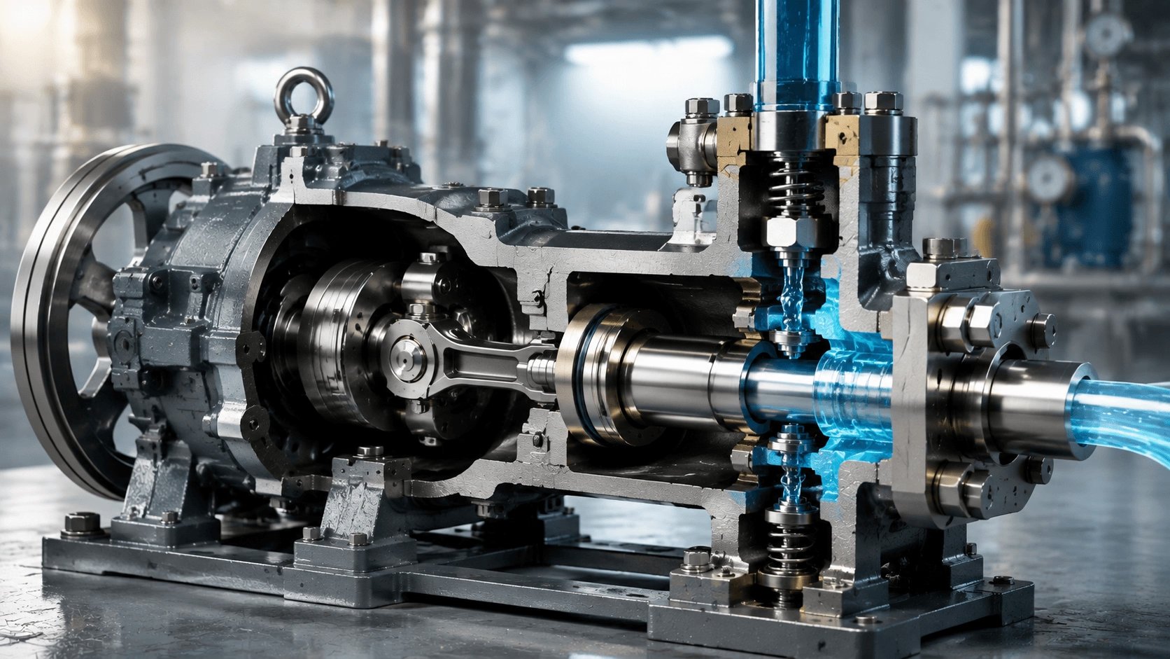
A comprehensive engineering guide to plunger pumps covering operating principles, displacement equations, valve dynamics, NPSH analysis, material selection, and ultra-high-pressure applications including waterjet cutting and well stimulation.
Table of Contents
- Introduction: The Apex of Pressure Generation
- Fundamental Operating Principle
- Theoretical Displacement & Flow Equations
- Classification of Plunger Pumps
- Core Engineering Equations
- Structural Design & Power End Engineering
- Valve Design & Dynamics
- Application Engineering & System Design
- Material Selection for Extreme Environments
- Maintenance & Reliability
- Energy Efficiency & Optimization
- Regulatory Standards & Certification
- Conclusion
- References & Standards
1. Introduction: The Apex of Pressure Generation
Plunger pumps—also known as reciprocating positive displacement pumps—represent the most mechanically robust and pressure-capable category of fluid machinery. Unlike centrifugal pumps that generate pressure through kinetic energy conversion, plunger pumps use the linear reciprocating motion of a solid plunger within a precision-machined cylinder to directly compress and displace fluid. This fundamental mechanism enables plunger pumps to achieve pressures that no other pump type can approach, routinely operating at 100–1,500 bar and reaching 3,000+ bar in specialized applications such as waterjet cutting and isostatic pressing.
The global high-pressure plunger pump market exceeds $3.5 billion annually, serving critical sectors including oil & gas (well stimulation, water injection), waterjet cutting (3,000–6,000 bar), pressure washing (150–3,000 bar), reverse osmosis desalination (55–80 bar), and process industries (chemical injection, homogenization). Their ability to deliver precise, metered flow at extreme pressures, combined with excellent efficiency across a wide viscosity range, makes them irreplaceable in applications where pressure is the primary engineering challenge.
2. Fundamental Operating Principle
2.1 The Four-Stroke Cycle
A plunger pump operates through a repeating four-stroke cycle driven by a crankshaft, cam, or hydraulic actuator:
| Phase | Plunger Motion | Valve State | Chamber Action | Fluid Behavior |
|---|---|---|---|---|
| 1. Suction (Intake) | Retracts (away from head) | Suction OPEN; Discharge CLOSED | Volume increases; pressure decreases | Fluid drawn in via pressure differential |
| 2. Suction Valve Closure | Continues retraction to max extent | Suction CLOSES; Discharge CLOSED | Max volume; min pressure | Backflow prevented; chamber fully charged |
| 3. Discharge (Delivery) | Advances (toward head) | Suction CLOSED; Discharge OPEN | Volume decreases; pressure increases | Fluid compressed until discharge pressure exceeded; expelled |
| 4. Discharge Valve Closure | Reaches Top Dead Center (TDC) | Discharge CLOSES; Suction CLOSED | Min volume; max pressure | Backflow prevented; cycle ready to repeat |
Key Distinction: The plunger itself does not contact the fluid being pumped in most designs (unlike a piston, which has sealing rings and moves within the cylinder bore). Instead, the plunger extends through a packing seal into a plunger chamber or fluid end, creating a seal at the packing rather than at the plunger surface. This design allows the plunger to be made of extremely hard, wear-resistant material while the packing (which is consumable) handles the dynamic sealing.
3. Theoretical Displacement & Flow Equations
All formulas are presented in plain-text format for universal compatibility.
3.1 Single-Acting, Single-Cylinder Displacement
V_disp = A_plunger * s = (pi / 4) * D_plunger^2 * s
Where:
- V_disp = Displacement per crank revolution (m³/rev)
- A_plunger = Cross-sectional area of plunger (m²)
- D_plunger = Plunger diameter (m)
- s = Stroke length (m)
3.2 Theoretical Flow Rate
Q_theoretical = V_disp * N = (pi / 4) * D_plunger^2 * s * N
Where N = crankshaft speed (rev/s).
3.3 Multi-Plunger Pump Flow
Q_theoretical_total = n_plungers * (pi / 4) * D_plunger^2 * s * N
Where n_plungers = number of plungers (typically 1, 2, 3, 5, or 7).
3.4 Double-Acting Pump Flow
Q_theoretical_double = 2 * n_plungers * (pi / 4) * D_plunger^2 * s * N
Note: The rod-side displacement is slightly less due to rod cross-sectional area.
Design Insight: Flow rate is directly proportional to plunger area, stroke length, speed, and number of plungers. Unlike centrifugal pumps, flow is independent of discharge pressure (within mechanical and volumetric limits), making plunger pumps ideal for metering and process control applications.
4. Classification of Plunger Pumps
4.1 By Drive Mechanism
| Drive Type | Mechanism | Speed Range | Pressure Range | Efficiency | Application |
|---|---|---|---|---|---|
| Crankshaft (Mechanical) | Motor/engine drives crankshaft via gears/belt | 100–500 RPM | 100–1,500 bar | 85–94% | Most common; industrial; mobile |
| Hydraulic Drive | Hydraulic cylinder actuates plunger directly | 10–100 strokes/min | 500–3,000+ bar | 80–88% | Ultra-high pressure; waterjet; isostatic pressing |
| Pneumatic Drive | Air cylinder drives plunger | 10–60 strokes/min | 50–500 bar | 60–75% | Explosion-proof; portable; low-cost |
| Linear Motor (Direct) | Electromagnetic linear actuator | 50–300 strokes/min | 100–500 bar | 75–85% | Precision metering; clean room; medical |
| Solenoid Drive | Electromagnetic plunger actuation | 1–20 strokes/min | 10–100 bar | 50–65% | Dosing; chemical injection; analytical |
| Cam Drive | Rotating cam profile drives follower/plunger | 100–1,000 RPM | 50–200 bar | 80–88% | Metering; process; uniform flow |
4.2 By Number of Plungers & Arrangement
| Configuration | Count | Phasing | Pulsation Level | Flow Smoothness | Typical Application |
|---|---|---|---|---|---|
| Simplex | 1 | N/A | Very High | Very Poor | Small metering; laboratory; hand-operated |
| Duplex | 2 | 180° | High | Poor | Small industrial; pressure washing; chemical feed |
| Triplex | 3 | 120° | Moderate | Good | Most common industrial; oil & gas; waterjet |
| Quintuplex | 5 | 72° | Low | Very Good | Large flow; pipeline; minimal pulsation |
| Septuplex | 7 | 51.4° | Very Low | Excellent | Maximum flow smoothness; sensitive equipment |
Pulsation Frequency:
f_pulsation = N * n_plungers
Example: A triplex pump at 350 RPM: f_pulsation = 350 × 3 = 1,050 pulses/min = 17.5 Hz.
Flow Pulsation Amplitude:
| Plunger Count | Theoretical Pulsation (% of mean flow) | Practical Pulsation (with dampener) |
|---|---|---|
| 1 (Simplex) | ±100% | ±80–95% |
| 2 (Duplex) | ±50% | ±30–40% |
| 3 (Triplex) | ±14% | ±5–10% |
| 5 (Quintuplex) | ±5% | ±2–4% |
| 7 (Septuplex) | ±2.5% | ±1–2% |
Industry Standard: Triplex pumps dominate because they offer an optimal balance of mechanical simplicity, flow smoothness, and cost. The 120° phasing creates overlapping discharge strokes that maintain relatively continuous flow, while the three-throw crankshaft is statically and dynamically balanced, minimizing vibration.
5. Core Engineering Equations
5.1 Pressure-Force Relationship
F_plunger = P_discharge * A_plunger = P_discharge * (pi / 4) * D_plunger^2
Crankshaft Torque:
T(theta) = F_plunger * r_crank * sin(theta) * [cos(theta) / sqrt(1 - lambda^2 * sin^2(theta))]
Simplified Average Torque (per plunger):
T_avg = (F_plunger * r_crank) / 2 = (P_discharge * A_plunger * s) / 4
Total Torque (Multi-Plunger):
T_total = (P_discharge * A_plunger * s * n_plungers) / (4 * eta_mechanical)
Critical Design Insight: Plunger force increases with the square of plunger diameter at constant pressure. A 20% increase in plunger diameter increases force by 44%, requiring proportionally stronger crankshafts, bearings, and frames. This is why high-pressure pumps use small-diameter plungers (10–50 mm) rather than large pistons.
5.2 Power Requirement
P_hydraulic = Q_actual * delta_P

P_shaft = P_hydraulic / (eta_volumetric * eta_mechanical)

P_motor = P_shaft / eta_motor
| Component | Efficiency Range | Factors Affecting |
|---|---|---|
| Volumetric | 85–98% | Valve leakage; packing leakage; compressibility; valve timing |
| Mechanical | 85–95% | Bearing friction; crosshead friction; packing friction; gear/belt losses |
| Total (Pump) | 75–92% | Combined; typically 80–88% for well-designed triplex |
| Motor | 88–96% (IE3–IE4) | Motor size; speed; load factor |
| Wire-to-Water | 70–85% | Overall system efficiency |
5.3 Volumetric Efficiency & Slip
| Loss Mechanism | Cause | Magnitude | Mitigation |
|---|---|---|---|
| Packing Leakage | Fluid bypasses plunger through packing seal | 1–5% (new); 5–15% (worn) | Proper packing selection; correct gland load; maintenance |
| Valve Leakage | Backflow through valves when closed | 0.5–2% (new); 2–8% (worn) | Hardened seats; proper spring force; clean fluid |
| Fluid Compressibility | Compression under high pressure before valve opens | 0.5–3% (water @ 1,000 bar) | Pre-compression design; minimize dead volume |
| Valve Timing (Late Closing) | Suction valve closes after discharge stroke begins | 1–5% | Optimize valve dynamics; spring rate; minimize mass |
| Dead Volume | Unswept volume at TDC reduces effective displacement | 0.5–2% | Minimize clearance; tapered plunger design |
Compressibility Correction (High Pressure):
Q_actual = Q_theoretical * (1 - delta_P / K_bulk)
At 1,000 bar (100 MPa), water compressibility loss is ~4.5%—a dominant design consideration for ultra-high-pressure pumps.
5.4 Plunger Velocity & Acceleration Effects
| Parameter | Effect of High Acceleration | Design Response |
|---|---|---|
| Inertial Forces | High forces on crosshead, bearings, frame | Robust frame; limit speed; balance reciprocating masses |
| Valve Dynamics | Valve must close before plunger reverses | Optimize valve mass, spring rate, lift height |
| Cavitation at Suction | Rapid acceleration creates low pressure spikes | Increase NPSHa; reduce speed; optimize suction valve |
| Flow Pulsation | Velocity variation creates pressure pulsation | More plungers; pulsation dampeners; accumulators |
| Vibration | Unbalanced reciprocating forces | Counterweights; multicylinder phasing; rigid mounting |
5.5 NPSH & Suction Conditions
Plunger pumps have unique NPSH requirements due to intermittent, accelerating suction flow. The acceleration head is the most critical factor:
H_acceleration ≈ (L_suction * s * N^2) / (1800 * g) [Simplified for Triplex]
Design Rule: NPSHa >= 2.0 * NPSHr (higher margin required due to acceleration effects)
Mitigation Strategies:
- Short suction lines: Minimize L_suction to reduce acceleration head.
- Oversized suction pipe: Reduce V_suction and friction losses.
- Suction stabilizer: Pneumatic or bladder accumulator at pump inlet absorbs acceleration pulses.
- Speed limitation: Lower speed reduces acceleration head proportionally to N².
6. Structural Design & Power End Engineering
6.1 The Power End (Drive Mechanism)
| Component | Function | Design Considerations | Material |
|---|---|---|---|
| Crankshaft | Converts rotary to reciprocating motion | Fatigue strength; torsional vibration; journal size | Forged steel; nitrided or induction hardened |
| Connecting Rod | Transmits force from crankshaft to crosshead | Buckling resistance; bearing ratio; weight | Forged steel; bronze small end bearing |
| Crosshead | Guides plunger linearly; absorbs side loads | Wear resistance; alignment; lubrication | Cast iron; bronze; steel with babbitt lining |
| Frame / Housing | Supports components; contains lubrication | Rigidity; fatigue resistance; vibration damping | Cast iron; fabricated steel; nodular iron |
6.2 The Fluid End (Wetted Components)
| Component | Function | Design Challenge | Material |
|---|---|---|---|
| Cylinder / Liner | Contains fluid; guides plunger | Wear; corrosion; cavitation; thermal fatigue | Hardened steel; ceramic; tungsten carbide coating |
| Plunger | Displaces fluid; withstands pressure | Surface finish; hardness; alignment; thermal expansion | Tungsten carbide; ceramic; hardened stainless steel |
| Packing Seal | Dynamic seal between plunger and atmosphere | High-pressure sealing; wear; heat; chemical compatibility | Aramid fiber; PTFE; carbon; PEEK; composites |
| Suction/Discharge Valve | Opens/closes during strokes | Rapid response; positive seal; wear resistance | Stainless steel; hastelloy; ceramic; coated steel |
| Manifold / Head | Collects discharge; distributes suction | Pressure containment; fatigue; corrosion; flow distribution | Forged steel; stainless steel; duplex; super duplex |
6.3 Plunger Design & Materials
| Material | Hardness | Wear Resistance | Corrosion Resistance | Cost | Application |
|---|---|---|---|---|---|
| Hardened Stainless Steel | 38–42 HRC | Good | Good | Low | General industrial; water; mild chemicals |
| Chrome-Plated Steel | 65–72 HRC | Very Good | Good | Low–Mod | Standard industrial; water; oil |
| Ceramic (Al₂O₃, ZrO₂) | 85+ HRC | Excellent | Excellent | Moderate | Abrasive; corrosive; high temperature |
| Tungsten Carbide (WC-Co) | 88–92 HRA | Exceptional | Good | High | Ultra-abrasive; high pressure; extended life |
Surface Finish Criticality: A 50% improvement in surface finish (e.g., from 0.4 µm to 0.2 µm Ra) can double or triple packing life by reducing abrasive wear and allowing the packing to conform more effectively. Ultra-high-pressure applications require 0.05–0.2 µm Ra achieved via superfinishing and lapping.
6.4 Packing Seal Technology
The packing seal is the most critical and most frequently replaced component. It must seal against high pressure, accommodate millions of cycles, resist chemical attack, dissipate frictional heat, and allow minimal leakage for cooling.
| Packing Type | Construction | Pressure Range | Temperature | Life | Application |
|---|---|---|---|---|---|
| Braided Fiber | Interwoven fibers with lubricant | ≤500 bar | -50 to +150°C | Moderate | General industrial; water; chemicals |
| Molded Composite | Molded rings with fabric reinforcement | ≤1,000 bar | -50 to +200°C | Good | High pressure; oil & gas; process |
| Chevron (V-Ring) | Multiple V-shaped rings in set | ≤700 bar | -30 to +120°C | Good | Hydraulic; medium pressure |
| Metal Bellows Seal | Welded metal bellows (no elastomer) | ≤2,000 bar | -200 to +400°C | Excellent | High temp; cryogenic; ultra-high purity |
7. Valve Design & Dynamics
7.1 Valve Types for Plunger Pumps
| Valve Type | Construction | Speed Capability | Pressure Capability | Application |
|---|---|---|---|---|
| Ball Valve | Spherical ball on seat; spring-loaded | Moderate (≤300 RPM) | ≤500 bar | Small pumps; metering; chemical feed |
| Disc (Poppet) Valve | Flat/conical disc on seat; spring-loaded | High (≤500 RPM) | ≤1,500 bar | Most common; triplex; industrial |
| Plate Valve | Multi-ring plate with spring; large flow area | High (≤400 RPM) | ≤1,000 bar | Large flow; low resistance; water |
| Active Valve (Solenoid) | Electromagnetically actuated | Very High (unlimited) | ≤200 bar | Precision metering; digital control; research |
7.2 Valve Dynamics Requirement
The valve must open and close within the available time window. For a triplex pump at 350 RPM, the available time per valve event is ~57 ms, requiring a valve actuation time of < 17 ms (applying a 0.3 safety margin). Valve design must balance low mass (fast response), adequate flow area (low pressure drop), and positive sealing (minimal leakage).
8. Application Engineering & System Design
8.1 System Design Fundamentals
| Element | Design Consideration | Plunger Pump Specific Requirement |
|---|---|---|
| Suction Line | Short, large diameter, minimal fittings | Critical due to acceleration head; suction stabilizer strongly recommended |
| Discharge Line | Sized for velocity < 3 m/s; rated for 1.5× max pressure | Water hammer protection; pulsation dampener essential |
| Relief Valve | Mandatory; set 10% above operating pressure | CRITICAL: Plunger pumps generate infinite pressure if blocked; catastrophic failure without relief |
| Pulsation Dampener | Bladder or piston type; sized per API 674 | Reduces pulsation 70–90%; protects piping and downstream equipment |
8.2 Pressure Washer System Design
| Parameter | Light Duty | Medium Duty | Heavy Duty | Ultra-Heavy Duty |
|---|---|---|---|---|
| Pressure | 50–150 bar | 150–300 bar | 300–500 bar | 500–3,000 bar |
| Plunger Material | Chrome-plated steel | Ceramic-coated steel | Tungsten carbide | Tungsten carbide / ceramic |
| Pump Type | Triplex; direct drive | Triplex; belt drive | Triplex; gearbox | Triplex; gearbox |
8.3 Oil & Gas Well Stimulation
| Parameter | Fracturing (Fracking) | Acidizing | Water Injection |
|---|---|---|---|
| Pressure | 500–1,200 bar | 200–700 bar | 150–400 bar |
| Fluid | Proppant slurry (sand + gel) | Acid (HCl, HF, organic) | Seawater; produced water; fresh water |
| Plunger Material | Tungsten carbide; ceramic | Hastelloy; titanium; ceramic | Chrome-plated; stainless steel |
| Pump Count | 10–50 pumps per fleet | 1–5 pumps | 1–10 pumps per station |
8.4 Waterjet Cutting
Waterjet intensifiers are a specialized application where a hydraulic-driven plunger pump (oil at 200 bar) drives a large-diameter piston coupled to a small-diameter water plunger. The pressure intensification follows:
P_water = P_oil * (D_large / D_small)^2
For a 20:1 intensifier with 200 bar hydraulic pressure: P_water = 200 * 20 = 4,000 bar.
9. Material Selection for Extreme Environments
9.1 Fluid End Material Matrix
| Material | Max Pressure | Corrosion Resistance | Abrasion Resistance | Application |
|---|---|---|---|---|
| Carbon Steel (Forged) | 1,500 bar | Poor (requires coating) | Moderate | Non-corrosive oil & gas; general industrial |
| Duplex SS 2205 | 1,200 bar | Excellent | Good | Seawater; aggressive chemicals; oil & gas |
| Hastelloy C-276 | 1,000 bar | Exceptional (acids) | Moderate | Strong acids; chlorine dioxide; chemical process |
| Titanium (Forged) | 800 bar | Exceptional | Good | Seawater; hypochlorite; ultra-pure water |
10. Maintenance & Reliability
10.1 Predictive Maintenance Schedule
| Method | Frequency | Indicators | Action Threshold |
|---|---|---|---|
| Packing Leakage Rate | Daily (visual) | Worn packing; misalignment; scored plunger | Exceeds 5 drops/min per plunger |
| Vibration Analysis | Monthly | Bearing wear; loose components; valve impact | ISO 10816 limits; new tonal frequencies |
| Oil Analysis (Power End) | Quarterly | Bearing wear; lubricant degradation; contamination | Fe > 50 ppm; viscosity change > 10%; water > 500 ppm |
| Valve Inspection | 2,000–4,000 hours | Seat wear; spring fatigue; corrosion; buildup | Visible wear > 0.5 mm; spring set > 10% |
10.2 Common Failure Modes & Diagnostics
| Symptom | Probable Cause | Corrective Action |
|---|---|---|
| Flow Loss / Pressure Drop | Worn packing; worn valves; suction problems | Replace packing/valves; verify drive; address suction NPSHa |
| Excessive Packing Leakage | Worn packing; scored plunger; misalignment; wrong material | Replace packing; polish/replace plunger; realign; adjust gland torque |
| Valve Knocking / Noise | Worn valve seat; broken spring; debris; slow closure | Replace valve/seat; replace spring; clean thoroughly; optimize spring rate |
| Excessive Vibration | Worn bearings; loose bolts; unbalanced crankshaft; cavitation | Replace bearings; tighten bolts; rebalance; realign; increase NPSHa |
11. Energy Efficiency & Optimization
11.1 Efficiency Comparison: Plunger vs. Other Pump Types
| Parameter | Centrifugal | Rotary PD | Plunger (Triplex) | Advantage |
|---|---|---|---|---|
| Peak Efficiency | 75–88% | 70–92% | 80–92% | Plunger (high pressure) |
| High-Pressure Eff. (>100 bar) | Poor (<50%) | Moderate (60–80%) | Excellent (80–92%) | Plunger |
| Precision Metering | Poor | Excellent | Excellent | Plunger / Rotary PD |
| Pressure Capability | <200 bar (typical) | <100 bar (typical) | 1,000–4,000+ bar | Plunger |
11.2 Energy Optimization Strategies
- Speed Reduction: Gearbox or VFD to match actual demand; 20–40% savings for variable demand.
- Variable Stroke: Adjustable eccentric or hydraulic drive; 15–30% savings.
- Packing Optimization: Correct material, proper load, regular maintenance; 5–10% savings by reducing friction and leakage.
- Pulsation Dampening: Properly sized suction/discharge dampeners; 5–15% savings by reducing acceleration head and smoothing flow.
12. Regulatory Standards & Certification
| Standard | Scope | Key Requirements for Plunger Pumps |
|---|---|---|
| API 674 | Positive displacement pumps—Reciprocating | Design; materials; pulsation control; vibration limits; testing; documentation |
| API 675 | Positive displacement pumps—Controlled volume | Metering pump specific; accuracy; repeatability; control |
| ASME BPVC VIII | Pressure vessel design | Fluid end pressure containment; safety factors; material certification |
| NACE MR0175 / ISO 15156 | Materials for sour service (H₂S) | Material hardness limits; sulfide stress cracking resistance |
| ATEX / IECEx | Explosion protection | Certification for flammable fluid handling; motor and control certification |
13. Conclusion
Plunger pumps stand at the apex of pressure generation technology. Their direct mechanical displacement mechanism—converting the linear reciprocating motion of a precision plunger into fluid compression—achieves pressures and efficiencies that no other pump type can match. From the 3,000-bar waterjet that slices through titanium to the 1,000-bar fracturing pump that unlocks shale oil reserves, plunger pumps enable industrial capabilities that define modern engineering.
The design of plunger pumps demands mastery of extreme-pressure mechanics, tribology, valve dynamics, material science, and pulsation control. Every component—from the crankshaft that withstands millions of fatigue cycles to the packing seal that maintains integrity across billions of reciprocating strokes—must be engineered for reliability under conditions that would rapidly destroy lesser machinery.
As industries pursue higher efficiency and lower emissions, the plunger pump is evolving through electrification (e-frac), advanced materials (ceramics, coatings), digital intelligence (smart monitoring, predictive maintenance), and system integration (energy recovery, closed-loop systems). The future of high-pressure fluid handling is not about replacing the plunger pump—it is about making it smarter, cleaner, and more sustainable while preserving the fundamental mechanical advantage that has made it indispensable for over a century.
References & Standards
- API 674 — Positive Displacement Pumps—Reciprocating
- API 675 — Positive Displacement Pumps—Controlled Volume
- ISO 16330:2003 — Reciprocating Positive Displacement Pumps
- ASME Boiler and Pressure Vessel Code, Section VIII — Pressure Vessels
- NACE MR0175 / ISO 15156 — Petroleum and Natural Gas Industries—Materials for Use in H₂S-Containing Environments
- Hydraulic Institute Standards for Reciprocating Pumps
- Reciprocating Pumps, John E. Miller — Comprehensive design and application reference
- High-Pressure Pumps, Michael T. Grace — Waterjet, intensifier, and ultra-high-pressure technology
Disclaimer: This article is intended for engineering professionals and technical buyers evaluating high-pressure pumping solutions. For application-specific pump selection, system design support, or custom engineering consultation, please contact your qualified technical team.