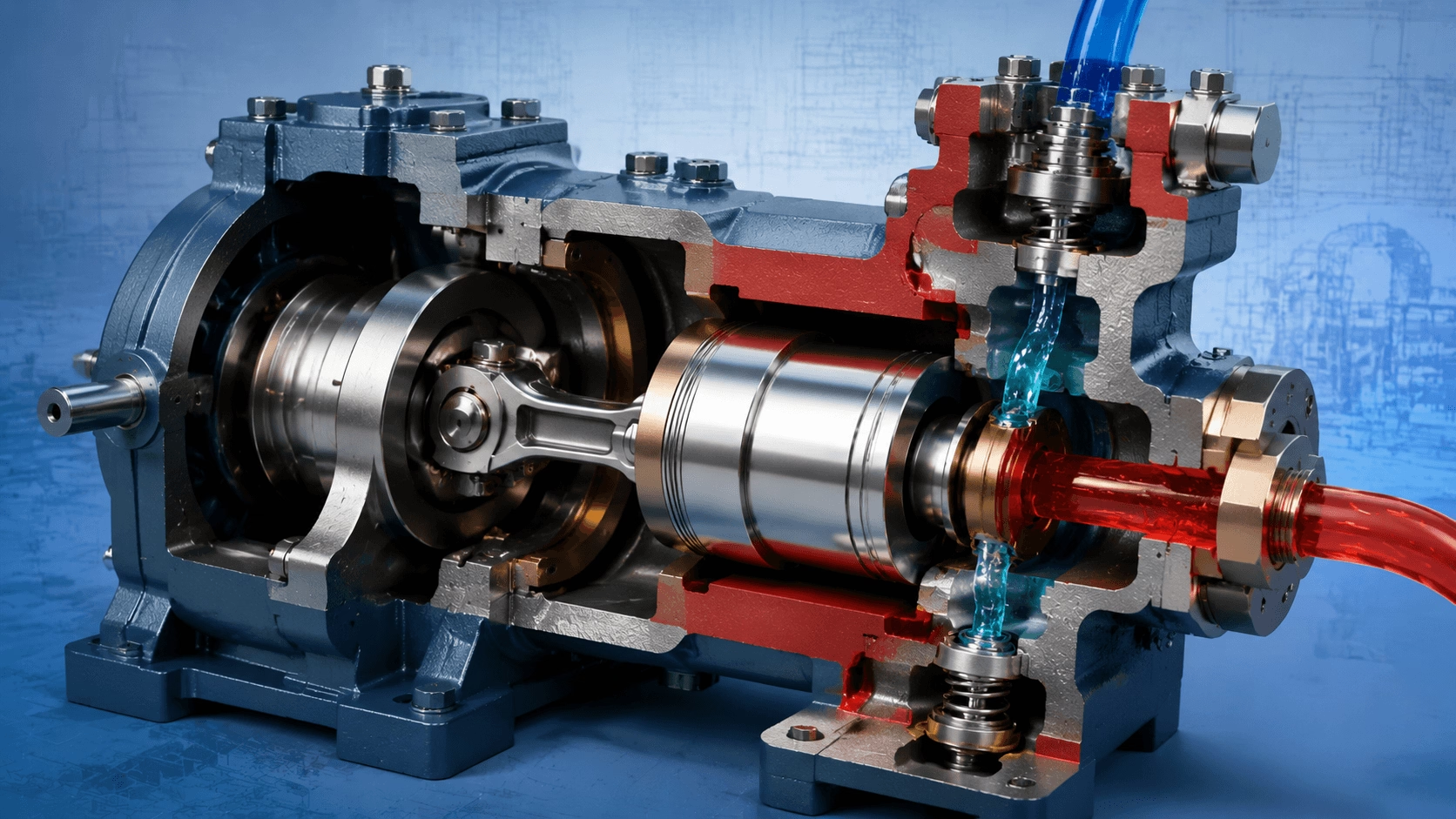
A technical deep-dive into piston pump principles, displacement equations, seal friction analysis, hydraulic performance, material selection, and applications ranging from precision metering to industrial hydraulics.
Table of Contents
- Introduction: Precision Displacement for Demanding Applications
- Fundamental Operating Principle
- Theoretical Displacement & Flow Equations
- Classification of Piston Pumps
- Core Engineering Equations
- Piston vs. Plunger Pump: Engineering Comparison
- Structural Design & Power End Engineering
- Piston Seal Technology
- Application Engineering
- Material Selection
- Maintenance & Reliability
- Energy Efficiency & Optimization
- Regulatory Standards & Certification
- Conclusion
- References & Standards
1. Introduction: Precision Displacement for Demanding Applications
Piston pumps are a fundamental class of reciprocating positive displacement pumps that use a sealed piston moving within a cylindrical chamber to displace fluid. Unlike plunger pumps—where the seal is stationary and the plunger slides through it—piston pumps integrate the dynamic seal directly onto the piston itself, which moves in unison within the cylinder bore. This design distinction fundamentally alters the pump's pressure capability, material constraints, maintenance profile, and optimal application space.
While plunger pumps dominate ultra-high-pressure applications (1,000+ bar), piston pumps excel in medium-pressure, high-flow, and metering applications where their integrated sealing design offers distinct advantages in compactness, self-priming capability, and suitability for viscous or solids-laden fluids. Key industries include hydraulic power systems, chemical processing, food & beverage, pharmaceutical manufacturing, automotive fuel injection, and high-precision metering.
This article provides a comprehensive technical analysis of piston pump mechanics, hydraulic design, sealing technology, and application engineering.
2. Fundamental Operating Principle
2.1 The Piston Pump Cycle
A piston pump operates through a repeating cycle where a piston, fitted with dynamic seals (rings or O-rings), reciprocates within a precision cylinder bore:
| Phase | Piston Motion | Valve State | Chamber Action | Fluid Behavior |
|---|---|---|---|---|
| 1. Suction | Retracts (away from head) | Suction OPEN; Discharge CLOSED | Volume increases; pressure drops | Fluid drawn in via pressure differential |
| 2. Suction Closure | Reaches Bottom Dead Center (BDC) | Suction CLOSES; Discharge CLOSED | Max volume; fully charged | Backflow prevented; compression begins |
| 3. Compression & Discharge | Advances (toward head) | Suction CLOSED; Discharge OPEN | Volume decreases; fluid compressed | Fluid expelled at system pressure |
| 4. Discharge Closure | Reaches Top Dead Center (TDC) | Discharge CLOSES; Suction CLOSED | Min volume (clearance) | Backflow prevented; cycle repeats |
Key Distinction from Plunger Pumps: In a piston pump, the seal is attached to the piston and moves with it inside the cylinder housing. The cylinder wall must therefore be smooth, hard, and dimensionally stable. In a plunger pump, the seal is stationary, allowing the plunger to be made of extremely hard materials (ceramic, tungsten carbide) while the cylinder wall has less stringent surface requirements.
3. Theoretical Displacement & Flow Equations
All formulas are presented in plain-text format for universal compatibility.
3.1 Single-Acting, Single-Cylinder Displacement
V_disp = A_piston * s = (pi / 4) * D_piston^2 * s
Where:
- V_disp = Displacement per crank revolution (m³/rev)
- A_piston = Cross-sectional area of piston (m²)
- D_piston = Piston diameter (m)
- s = Stroke length (m)
3.2 Theoretical Flow Rate
Q_theoretical = V_disp * N = (pi / 4) * D_piston^2 * s * N
Where N = crankshaft speed (rev/s).
3.3 Multi-Piston Pump Flow
Q_theoretical_total = n_pistons * (pi / 4) * D_piston^2 * s * N
Where n_pistons = number of pistons (typically 1, 2, 3, 5, 7, or 9).
3.4 Double-Acting Piston Pump Flow
Q_theoretical_double = n_pistons * (pi / 4) * (2*D_piston^2 - D_rod^2) * s * N
Where D_rod = piston rod diameter (m). The rod-side displacement is reduced by the rod cross-sectional area.
Design Insight: Piston pumps can achieve higher flow rates per unit of frontal area than plunger pumps because the piston diameter is not constrained by the need to pass through a stationary seal.
4. Classification of Piston Pumps
4.1 By Drive Mechanism
| Drive Type | Mechanism | Speed Range | Pressure Range | Efficiency | Application |
|---|---|---|---|---|---|
| Crankshaft | Motor/engine drives crankshaft | 100–1,800 RPM | 10–700 bar | 85–92% | Industrial; mobile hydraulic |
| Cam Drive | Rotating cam drives follower | 100–3,000 RPM | 10–200 bar | 80–88% | Metering; uniform flow |
| Swashplate (Axial) | Angled plate drives pistons axially | 1,500–3,000 RPM | 50–450 bar | 90–95% | Hydraulic power; mobile |
| Bent-Axis (Axial) | Cylinder block angled to shaft | 1,500–3,000 RPM | 50–700 bar | 90–95% | High-power hydraulics; marine |
| Radial | Pistons radial around eccentric | 500–1,500 RPM | 50–700 bar | 88–93% | High torque; low speed |
| Pneumatic | Air cylinder drives piston | 10–200 strokes/min | 10–100 bar | 60–75% | Explosion-proof; portable |
| Solenoid | Electromagnetic actuation | 1–100 strokes/min | 1–50 bar | 50–70% | Precision dosing; medical |
4.2 By Number of Pistons & Arrangement
| Configuration | Count | Phasing | Pulsation | Flow Smoothness | Typical Application |
|---|---|---|---|---|---|
| Simplex | 1 | N/A | Very High | Very Poor | Hand pumps; lab metering |
| Duplex | 2 | 180° | High | Poor | Chemical feed; small hydraulic |
| Triplex | 3 | 120° | Moderate | Good | Industrial process; fuel injection |
| Quintuplex | 5 | 72° | Low | Very Good | Pipeline; minimal pulsation |
| Septuplex | 7 | 51.4° | Very Low | Excellent | Sensitive equipment |
| Axial | 5–11 | Even | Very Low | Excellent | Hydraulic power packs |
Pulsation Frequency:
f_pulsation = N * n_pistons
Where f_pulsation = pulses per minute.
4.3 By Pump Action
| Action Type | Description | Flow per Rev | Efficiency | Application |
|---|---|---|---|---|
| Single-Acting | Displacement on forward stroke only | V_disp | 85–90% | General industrial; metering |
| Double-Acting | Displacement on both strokes | ~2× V_disp | 88–92% | High flow; hydraulic power |
| Differential | Rod-side suction; full-area discharge | Intermediate | 85–90% | Compact hydraulic circuits |
5. Core Engineering Equations
5.1 Pressure-Force Relationship
F_piston = P_discharge * A_piston = P_discharge * (pi / 4) * D_piston^2
Crankshaft Torque (Simplified):
T_avg = (F_piston * r_crank) / 2 = (P_discharge * A_piston * s) / 4
Total Torque (Multi-Piston):
T_total = (P_discharge * A_piston * s * n_pistons) / (4 * eta_mechanical)
Critical Design Insight: Seal friction adds significant parasitic load. The seal must be compressed against the cylinder wall, creating friction that opposes motion. At high pressure, seal friction can consume 10–20% of input power and cause rapid degradation, limiting piston pumps to lower pressures than plunger pumps.
5.2 Seal Friction Analysis
F_friction_seal = mu_seal * F_contact

F_contact = F_preload + P_discharge * A_projected_seal

eta_mechanical_effective = [(F_piston - F_friction_seal) / F_piston] * eta_bearing
Where mu_seal = coefficient of friction (0.05–0.30). At high pressure, F_friction_seal becomes dominant, explaining why piston pumps are typically rated below 700 bar.
5.3 Power Requirement
P_hydraulic = Q_actual * delta_P

P_shaft = P_hydraulic / (eta_volumetric * eta_mechanical)

P_motor = P_shaft / eta_motor
| Component | Efficiency Range | Factors Affecting |
|---|---|---|
| Volumetric | 85–95% | Ring leakage; valve leakage; clearance; compressibility |
| Mechanical | 80–92% | Seal friction; bearing friction; viscous drag |
| Total (Pump) | 75–88% | Typically 80–85% for well-designed triplex |
| Motor | 88–96% (IE3–IE4) | Size; speed; load factor |
| Wire-to-Water | 68–82% | Overall system efficiency |
5.4 Volumetric Efficiency & Leakage Paths
| Loss Mechanism | Cause | Magnitude | Mitigation |
|---|---|---|---|
| Piston Ring Leakage | Bypass through ring grooves | 1–8% (new); 5–15% (worn) | Proper ring design; correct end gap |
| Valve Leakage | Backflow through valves | 0.5–2% (new); 2–8% (worn) | Hardened seats; proper spring force |
| Compressibility | Compression before valve opens | 0.5–3% (water @ 700 bar) | Minimize clearance; pre-compression |
| Clearance Volume | Unswept volume at TDC | 1–3% | Tapered piston; minimize TDC gap |
| Blow-by | High-pressure fluid past rings | 2–10% (gas); 1–5% (liquid) | Multiple rings; stepped designs |
Volumetric Efficiency Equation:
eta_vol = Q_actual / Q_theoretical = 1 - [(Q_slip_rings + Q_slip_valve + Q_compressibility) / Q_theoretical]
5.5 Piston Velocity & Acceleration
v(theta) = omega * r_crank * [sin(theta) + (lambda * sin(2*theta)) / (2 * sqrt(1 - lambda^2 * sin^2(theta)))]

v_max ≈ omega * r_crank = pi * N * s

a_max = omega^2 * r_crank * (1 + lambda)
| Parameter | Effect | Design Response |
|---|---|---|
| High Acceleration | Inertial forces on piston/rings/valves | Limit speed; lightweight piston; balance masses |
| Side Thrust | Piston presses against cylinder wall | Crosshead design; anti-friction coatings |
| Ring Flutter | Rings lose contact at high speed | Limit speed; increase ring tension |
| Cavitation | Rapid suction acceleration | Increase NPSHa; reduce speed; optimize valve |
5.6 NPSH & Suction Conditions
NPSHr = (V_suction_max^2 / 2g) + Hf_suction + H_acceleration + H_valve

H_acceleration ≈ (L_suction * s * N^2) / (1800 * g)   [Triplex Piston Pump]
Design Rule: NPSHa >= 1.5 * NPSHr (piston pumps tolerate slightly lower margins than plunger pumps due to smoother suction profile).
6. Piston vs. Plunger Pump: Engineering Comparison
| Parameter | Piston Pump | Plunger Pump | Engineering Rationale |
|---|---|---|---|
| Seal Location | On piston (moving) | Stationary (cylinder head) | Defines all other differences |
| Max Pressure | 10–700 bar | 100–4,000+ bar | Seal friction limits piston pumps |
| Seal Friction | Higher (10–20% of power) | Lower (3–8% of power) | Moving seal creates drag on cylinder wall |
| Cylinder Material | Must be hard, smooth, wear-resistant | Less critical | Piston seal rides on cylinder wall |
| Piston/Plunger Material | Aluminum, steel, coated steel | Ceramic, tungsten carbide | Plunger can be harder (no wall sealing) |
| Flow Capability | Higher per unit frontal area | Lower per unit frontal area | Piston diameter unconstrained by seal passage |
| Viscous Fluid Handling | Better (with proper rings) | Moderate | Rings handle viscosity better than packing |
| Solids Handling | Possible with special rings | Poor | Packing is sensitive to abrasives |
| Maintenance | More frequent (rings, oil baths) | Less frequent (packing only) | More wearing parts in piston pumps |
| Initial Cost | Lower for equivalent flow | Higher | Simpler construction at moderate pressure |
| Best Application | Medium pressure; high flow; hydraulics | Ultra-high pressure; abrasive; continuous duty | Complementary technologies |
7. Structural Design & Power End Engineering
7.1 The Power End
| Component | Function | Design Considerations | Material |
|---|---|---|---|
| Crankshaft | Rotary to reciprocating conversion | Fatigue strength; torsional vibration | Forged steel; nodular iron; nitrided |
| Connecting Rod | Force transmission | Buckling resistance; bearing ratio | Forged steel; aluminum (small) |
| Crosshead | Absorbs side thrust; guides rod | Wear resistance; alignment | Cast iron; bronze; babbitt-lined steel |
| Piston Rod | Connects crosshead to piston | Fatigue strength; surface finish | Hardened steel; stainless; chrome-plated |
| Frame / Housing | Support; lubrication containment | Rigidity; vibration damping | Cast iron; fabricated steel |
| Main Bearings | Crankshaft support | Load rating; L10 life | Rolling element; hydrodynamic journal |
| Gear Reducer | Speed matching | Efficiency; backlash; torque | Hardened steel; precision ground |
7.2 The Fluid End (Wetted Components)
| Component | Function | Design Challenge | Material |
|---|---|---|---|
| Cylinder / Liner | Contains fluid; guides piston | Wear; corrosion; surface finish | Hardened steel; ceramic-coated; chrome |
| Piston | Displaces fluid; carries seals | Weight; thermal expansion; wear | Aluminum; steel; stainless; coated |
| Piston Rings / Seals | Dynamic sealing | Pressure energization; heat; friction | Cast iron; PTFE; carbon; elastomer |
| Cylinder Head | Closes chamber; contains valves | Pressure containment; fatigue | Forged steel; stainless; ductile iron |
| Valves | Flow control | Rapid response; positive seal | Stainless steel; hastelloy; ceramic |
| Valve Seat | Sealing surface | Hardness; replaceability | Stellite; ceramic; tungsten carbide |
| Valve Spring | Closure timing | Fatigue life; rate matching | Stainless steel; Inconel |
8. Piston Seal Technology
The piston seal is the defining component. It must maintain dynamic sealing over millions of cycles, accommodate side thrust, resist extrusion, minimize friction, and allow for thermal expansion.
8.1 Seal Types
| Seal Type | Construction | Pressure Range | Temp Range | Friction | Life | Application |
|---|---|---|---|---|---|---|
| Piston Rings (Cast Iron) | Segmental; spring-expandable | ≤200 bar | -40 to +250°C | Moderate | Very Good | Hydraulic; compressor; steam |
| Piston Rings (PTFE) | Filled PTFE (bronze/graphite) | ≤400 bar | -50 to +200°C | Low | Good | Chemical; food-grade |
| O-Ring (Dynamic) | Elastomer toroid | ≤150 bar | -30 to +150°C | Moderate | Moderate | Low pressure; pneumatic |
| Cup Seal (U-Cup) | U-shaped elastomer/PTFE | ≤300 bar | -30 to +120°C | Low | Good | Hydraulic; single-acting |
| Chevron (V-Ring) | Multiple V-rings stack | ≤500 bar | -30 to +120°C | Moderate | Good | High-pressure hydraulic |
| Step Seal | PTFE + elastomer energizer | ≤400 bar | -50 to +200°C | Very Low | Very Good | High-speed; precision |
| Metal-to-Metal | Precision lapped surfaces | ≤1,000+ bar | Unlimited | Very Low | Excellent | Ultra-high pressure; research |
8.2 Piston Ring Design Parameters
End Gap (Installed):
Gap_min = pi * D_piston * alpha_thermal * delta_T_max
Typical end gap: 0.003–0.005 × D_piston (mm per mm of diameter).
Ring Contact Pressure:
P_contact = [E_ring * t_ring^3 / (4 * D_piston * (D_piston - t_ring)^2)] * delta_radial
Typical contact pressure: 0.05–0.15 MPa (standard); up to 0.3 MPa (high-pressure).
9. Application Engineering
9.1 Hydraulic Power Systems
| Parameter | Mobile Hydraulic | Industrial Hydraulic | Aerospace Hydraulic |
|---|---|---|---|
| Pressure | 200–350 bar | 150–315 bar | 210–420 bar |
| Flow | 20–200 L/min | 50–500 L/min | 5–50 L/min |
| Pump Type | Axial (swashplate) | Axial or Radial | Axial (variable) |
| Speed | 1,500–2,500 RPM | 1,000–1,800 RPM | 3,000–6,000 RPM |
| Efficiency | 90–95% | 90–95% | 88–93% |
| Control | Load-sensing | Pressure/Flow compensated | Electro-hydraulic; digital |
| Life Target | 5,000–10,000 hrs | 10,000–20,000 hrs | 5,000–10,000 hrs |
Axial Piston Displacement Control:
Q_theoretical = n_pistons * (pi / 4) * D_piston^2 * D_pitch * tan(gamma) * N
Varying swashplate angle (gamma) modulates flow from zero to full displacement without changing speed.
9.2 Chemical Metering & Dosing
| Parameter | Diaphragm-Protected | Direct Piston | Packless Piston |
|---|---|---|---|
| Pressure | 10–100 bar | 10–400 bar | 10–700 bar |
| Flow | 0.1–1,000 L/h | 1–10,000 L/h | 10–50,000 L/h |
| Accuracy | ±0.5–1% | ±1–2% | ±2–3% |
| Seal Type | Diaphragm (zero leak) | Rings / O-rings | Metal-to-metal; labyrinth |
| Maintenance | Very Low | Moderate | Low (precision-dependent) |
9.3 Food & Beverage Processing
| Parameter | Hygienic Piston Pump | Aseptic Piston Pump |
|---|---|---|
| Pressure | 10–50 bar | 10–30 bar |
| Material | SS 316L; FDA elastomers | SS 316L; PTFE; platinum silicone |
| Surface Finish | Ra ≤ 0.8 µm | Ra ≤ 0.4 µm |
| Seal Type | Sanitary O-rings; PTFE | Metal bellows; diaphragm |
| Certification | FDA; 3A; EHEDG | FDA; 3A; EHEDG; ASME BPE |
10. Material Selection
10.1 Piston Materials
| Material | Hardness | Weight | Thermal Expansion | Application |
|---|---|---|---|---|
| Aluminum Alloy (Anodized) | 200–400 HV | Very Low | High | Small pumps; aerospace |
| Cast Iron (Gray/Nodular) | 180–300 BHN | Moderate | Moderate | General industrial; hydraulic |
| Steel (Hardened) | 55–65 HRC | Moderate | Moderate | Medium pressure; wear resistance |
| Stainless Steel (17-4 PH) | 38–42 HRC | Moderate | Moderate | Corrosive fluids; food |
| Ceramic-Coated Steel | 1,200–1,800 HV | Moderate | Low (coating) | Abrasive; extended life |
| Chrome-Plated Steel | 800–1,200 HV | Moderate | Moderate | Standard industrial |
10.2 Cylinder Materials
| Material | Hardness | Wear Resistance | Corrosion Resistance | Application |
|---|---|---|---|---|
| Cast Iron (Hardened) | 200–400 BHN | Good | Poor | General industrial |
| Steel (Hardened/Ground) | 55–65 HRC | Very Good | Moderate | High pressure; precision |
| Stainless Steel 316L | 150–200 BHN | Moderate | Excellent | Food; pharma; chemical |
| Ceramic-Lined Steel | 1,500+ HV | Excellent | Excellent | Abrasive; ultra-pure |
| Chrome-Plated Steel | 800–1,200 HV | Very Good | Good | Standard industrial |
11. Maintenance & Reliability
11.1 Predictive Maintenance Schedule
| Method | Frequency | Indicators | Action Threshold |
|---|---|---|---|
| Ring Leakage Check | Weekly | Worn rings; scored cylinder | Blow-by > 5%; pressure drop > 10% |
| Oil Analysis | Quarterly | Bearing wear; contamination | Fe > 50 ppm; water > 500 ppm |
| Cylinder Wear Measurement | 4,000–8,000 hrs | Diameter increase; ovality | Wear > 0.05 mm; ovality > 0.02 mm |
| Piston Inspection | 4,000–8,000 hrs | Scoring; groove wear | Groove wear > 0.1 mm |
| Valve Inspection | 2,000–4,000 hrs | Seat wear; spring fatigue | Wear > 0.5 mm; spring set > 10% |
| Seal Replacement | 1,000–4,000 hrs | Leakage; hardening | Exceeds allowable leakage rate |
| Vibration Analysis | Monthly | Bearing wear; looseness | ISO 10816 limits exceeded |
11.2 Rebuild Intervals
| Component | Light Duty | Medium Duty | Heavy Duty | Rebuild Cost (% New) |
|---|---|---|---|---|
| Piston Rings | 2,000–4,000 hrs | 1,000–2,000 hrs | 500–1,000 hrs | 3–8% |
| Cylinder Liner | 8,000–16,000 hrs | 4,000–8,000 hrs | 2,000–4,000 hrs | 10–15% |
| Piston | 8,000–16,000 hrs | 4,000–8,000 hrs | 2,000–4,000 hrs | 8–12% |
| Valves | 8,000–16,000 hrs | 4,000–8,000 hrs | 2,000–4,000 hrs | 5–10% |
| Bearings | 16,000–32,000 hrs | 8,000–16,000 hrs | 4,000–8,000 hrs | 5–10% |
| Complete Rebuild | — | — | — | 35–55% |
12. Energy Efficiency & Optimization
12.1 Efficiency Comparison
| Parameter | Piston Pump | Plunger Pump | Centrifugal | Rotary PD |
|---|---|---|---|---|
| Peak Efficiency | 80–88% | 85–92% | 75–88% | 70–92% |
| Medium-Pressure Eff. (100–300 bar) | 80–88% | 82–90% | 60–75% | 75–85% |
| High-Pressure Eff. (>500 bar) | 70–80% | 85–92% | <50% | 60–75% |
| Seal Friction Loss | 5–15% | 2–5% | N/A | 3–8% |
| Best Efficiency Range | 50–400 bar | 200–2,000 bar | <100 bar | <50 bar |
12.2 Optimization Strategies
| Strategy | Implementation | Savings | Application |
|---|---|---|---|
| Variable Displacement | Adjust swashplate angle | 20–40% | Hydraulic power; mobile |
| Speed Control (VFD) | Match speed to demand | 15–30% | Process; metering |
| Low-Friction Seals | PTFE/composite rings | 5–10% | All applications |
| Cylinder Honing | Optimize surface finish | 3–8% | Rebuild; new manufacture |
| Proper Ring End Gap | Minimize blow-by | 3–5% | Ring-sealed applications |
| Pulsation Dampening | Suction/discharge accumulators | 5–10% | Multi-piston systems |
13. Regulatory Standards & Certification
| Standard | Scope | Key Requirements |
|---|---|---|
| ISO 16330 | Reciprocating PD pumps | Performance testing; safety; specs |
| API 674 | Reciprocating PD pumps | Design; materials; pulsation; vibration |
| API 675 | Controlled volume pumps | Accuracy; repeatability; calibration |
| ISO 4406 | Hydraulic fluid cleanliness | Contamination coding |
| ISO 11171 | Hydraulic filter testing | Filter performance verification |
| FDA 21 CFR 177 | Food contact materials | Elastomer/polymer approval |
| EU Machinery Directive | General machinery safety | CE marking; risk assessment |
| ATEX / IECEx | Explosion protection | Flammable environment certification |
14. Conclusion
Piston pumps occupy a critical and distinct position in positive displacement technology. While sharing the fundamental reciprocating principle with plunger pumps, their integrated moving seal design fundamentally shapes their capabilities and optimal applications.
Piston pumps excel where moderate pressure, high flow, compact design, and operational flexibility are required. Their ability to handle viscous fluids, self-prime effectively, and integrate into compact axial and radial configurations makes them indispensable in hydraulic power systems, precision metering, food processing, and fuel injection.
The engineering of piston pumps demands careful attention to seal friction management, cylinder surface integrity, and piston dynamics. Every design decision—from ring end gap to cylinder honing specification to swashplate angle—directly impacts efficiency, reliability, and service life.
Selection Decision Matrix:
- Choose Piston Pumps for: Medium pressure (10–400 bar), high flow, viscous fluids, compact hydraulic systems, and cost-sensitive applications.
- Choose Plunger Pumps for: High/ultra-high pressure (>400 bar), abrasive fluids, continuous duty, and applications where packing life outweighs initial cost.
As industries advance toward electrification and digitalization, piston pumps continue to evolve through variable displacement electro-hydraulic control, advanced composite materials, smart condition monitoring, and energy-efficient system integration.
References & Standards
- ISO 16330:2003 — Reciprocating Positive Displacement Pumps
- API 674 — Positive Displacement Pumps—Reciprocating
- API 675 — Positive Displacement Pumps—Controlled Volume
- ISO 4406 — Hydraulic Fluid Power—Fluids—Method for Coding Level of Contamination
- Hydraulic Pumps and Motors, Akers et al. — Axial and radial piston pump design
- Reciprocating Pumps, John E. Miller — Comprehensive design and application reference
- Piston Ring Design, Goetze — Seal engineering and tribology
Disclaimer: This article is intended for engineering professionals evaluating reciprocating pump technologies. For application-specific pump selection, system design support, or custom engineering consultation, please contact your qualified technical team.