Motor and Pump Installation Best Practices: Step-by-Step Guide | TITECHO
Abstract: A comprehensive, step-by-step technical guide for the installation of industrial AC motors and water pumps. This document details critical procedures including foundation preparation, precision alignment, piping configuration, electrical wiring, and commissioning protocols. Adherence to these TITECHO best practices ensures optimal performance, energy efficiency, and extended equipment service life.
1. Introduction: The Critical Role of Proper Installation
Even premium-quality motors and pumps are susceptible to premature failure if installed incorrectly. Proper installation is the foundational determinant of operational reliability, energy efficiency, and asset longevity.
This TITECHO guide outlines industry-standard best practices for installing industrial AC motors and centrifugal pumps, serving as a technical reference for engineers, technicians, and maintenance personnel.
2. Safety Protocols
Strict adherence to safety procedures is mandatory before commencing any installation activity:
- ⚠️ Lockout/Tagout (LOTO): Verify complete isolation and de-energization of all power sources before work begins.
- ⚠️ Personal Protective Equipment (PPE): Mandatory use of safety glasses, cut-resistant gloves, and steel-toed footwear.
- ⚠️ Lifting Safety: Utilize appropriately rated hoists and rigging for heavy equipment handling; never lift manually beyond safe limits.
- ⚠️ Documentation Review: Thoroughly review the manufacturer’s installation manual prior to beginning work.
3. Pre-Installation Inspection
Verify equipment integrity before mounting:
| Check | Required Action | Acceptance Criteria |
|---|---|---|
| Visual Inspection | Examine for shipping damage, corrosion, or loose components | No visible defects; all fasteners secure |
| Shaft Rotation | Manually rotate shaft by hand | Smooth, unrestricted rotation; no binding or noise |
| Insulation Resistance | Measure winding resistance with megohmmeter | > 1 MΩ at 500 VDC (or per manufacturer spec) |
| Nameplate Verification | Confirm voltage, frequency, and power rating | Exact match with site supply specifications |
4. Foundation and Mounting
A rigid, stable foundation is essential to minimize vibration transmission and maintain alignment.
Foundation Specifications
- Concrete Base Mass: Minimum 10 times the combined mass of the motor-pump assembly to dampen dynamic forces.
- Leveling Tolerance: Base surface must be flat within 0.5 mm/m, verified with precision machinist levels.
- Anchor Bolts: Use high-tensile bolts with locking washers. Grout base plates fully to eliminate voids and ensure uniform load distribution.
- Vibration Isolation: Install elastomeric pads or spring isolators when vibration transmission to surrounding structure must be minimized.
5. Mechanical Alignment
Misalignment is the leading cause of premature bearing and mechanical seal failure. Precision alignment is non-negotiable.
5.1 Misalignment Types
| Type | Description | Primary Consequence |
|---|---|---|
| Parallel (Offset) | Shaft centerlines are parallel but laterally displaced | Radial bearing loads, coupling wear |
| Angular | Shaft centerlines intersect at an angle | Axial thrust loading, seal face distortion |
| Combined | Both parallel and angular offset present simultaneously | Accelerated multi-axis degradation |
5.2 Alignment Procedure
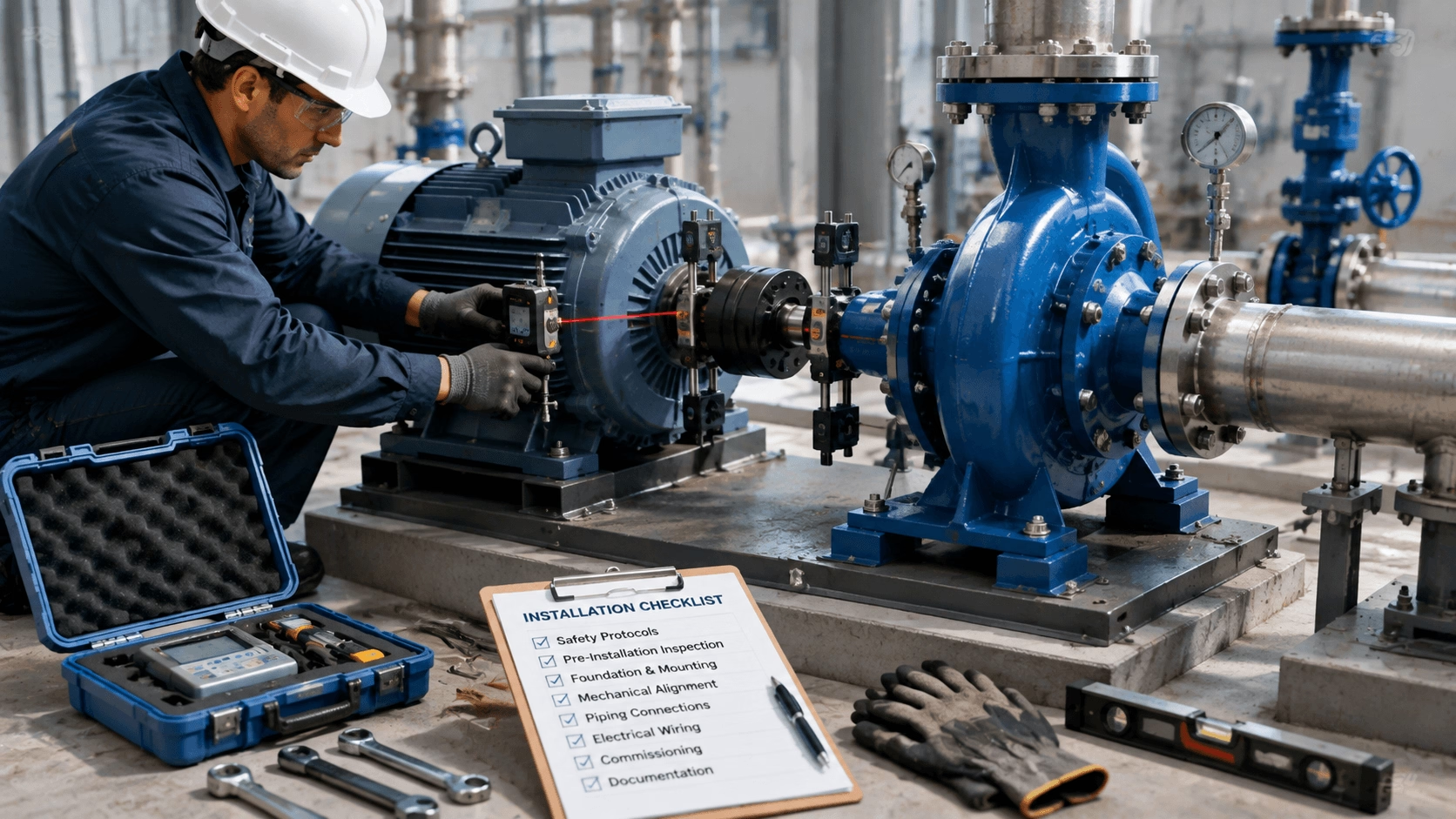
- Soft Foot Check: Verify all motor feet sit flush on the base without gaps. Shim as necessary before alignment.
- Rough Alignment: Use straightedge or feeler gauge to achieve approximate coupling alignment.
- Precision Alignment: Employ laser alignment system or dial indicators for final adjustment.
- Tolerance Target: Achieve alignment within 0.05 mm for high-speed applications (>1800 RPM); refer to OEM specifications for exact tolerances.
6. Piping Connections (Pump-Specific)
Improper piping induces mechanical stress that distorts pump casings and misaligns internal components.
Suction Side Requirements
- Pipe diameter equal to or larger than pump inlet flange.
- Short, straight run upstream of suction flange (minimum 5× pipe diameter).
- Slight upward slope toward pump to prevent air pocket formation.
- Eccentric reducer (flat side up) if pipe size transition is required.
Discharge Side Requirements
- Install check valve and isolation valve immediately downstream of pump.
- Gradual expansion fitting if discharge pipe is larger than pump outlet.
General Piping Rules
- Independent Support: All piping must be independently supported; zero pipe weight may rest on pump casing.
- Flexible Connectors: Use flexible couplings or expansion joints to isolate vibration and accommodate minor thermal movement.
- Strain-Free Connection: Flange bolts should tighten evenly without forcing alignment; if force is required, rework piping.
7. Electrical Wiring
| Step | Technical Requirement |
|---|---|
| Cable Sizing | Select conductor gauge based on full-load current and cable length; limit voltage drop to <3% |
| Terminal Connections | Torque all terminals to manufacturer specification; verify tightness after thermal cycling |
| Grounding | Secure earth ground connection per local electrical code; verify continuity |
| Protection Devices | Install correctly sized overload relays, circuit breakers, and phase-loss monitors |
| Rotation Verification | Perform bump test (momentary energization) to confirm correct rotation direction before final coupling |
8. Commissioning and Start-Up Protocol
- Pre-Start Preparation: Lubricate bearings (if not sealed-for-life); prime pump completely with process fluid.
- Valve Positioning: For centrifugal pumps, close discharge valve partially during start to limit inrush current.
- Energization: Start motor and immediately verify amperage against nameplate FLA.
- Flow Establishment: Gradually open discharge valve to reach desired operating point; avoid prolonged dead-head operation.
- Initial Monitoring: Continuously monitor vibration, noise, temperature, and seal leakage for minimum 60 minutes post-startup. Record baseline values.
9. Common Installation Mistakes and Prevention
| Mistake | Consequence | Prevention Strategy |
|---|---|---|
| Skipping Precision Alignment | Premature bearing/seal failure | Mandatory laser alignment with documented results |
| Pipe Strain on Casing | Housing distortion, shaft fatigue | Independent pipe supports; strain-free flange mating |
| Incorrect Lubricant | Bearing overheating or degradation | Follow OEM grease type and fill quantity specifications exactly |
| Dry Running | Catastrophic seal and impeller damage | Verified priming procedure; dry-run protection interlock |
| Loose Electrical Connections | Arc faults, phase loss, motor burnout | Calibrated torque wrench verification on all terminals |
10. Post-Installation Documentation
Maintain comprehensive records to support future maintenance and warranty validation:
- ✅ Precision alignment report with measured values
- ✅ Electrical test results (insulation resistance, phase balance)
- ✅ Installation date, technician identification, and sign-off
- ✅ Baseline vibration spectrum and temperature readings
- ✅ As-built piping diagram and valve schedule
11. Conclusion
Proper installation is the indispensable foundation of reliable, efficient, and long-lived pumping systems. Rigorous adherence to these best practices maximizes return on investment in TITECHO motors and pumps while minimizing unplanned downtime and lifecycle costs.
Installation Support Resources
- Download Installation Manuals & Checklists: www.cntecho.com
- Contact Support Engineers: [email protected]