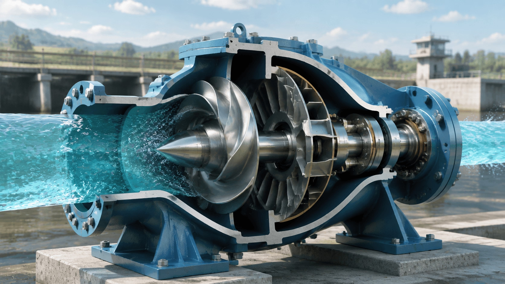
A comprehensive technical guide to mixed flow pumps covering operating principles, impeller hydraulics, essential formulas, efficiency characteristics, real-world applications, and systematic selection methodology for engineering and industrial use.
Table of Contents
- What Is a Mixed Flow Pump?
- The Key Advantage: Why Mixed Flow?
- Operating Principle & Impeller Design
- Essential Hydraulic Formulas
- Real-World Applications
- Step-by-Step Selection Methodology
- Performance Curve Characteristics
- Efficiency Comparison vs. Alternatives
- Common Myths Debunked
- Maintenance Fundamentals
- Unit Conversion Reference
- Conclusion
1. What Is a Mixed Flow Pump?
A mixed flow pump occupies the hydraulic middle ground between two fundamental pump families:
- Centrifugal (Radial) Pump: Discharges fluid at 90° to the shaft axis; optimized for high pressure and low flow.
- Axial Flow Pump: Discharges fluid parallel to the shaft axis; optimized for low pressure and massive flow.
- Mixed Flow Pump: Discharges fluid at an intermediate angle (typically 30°–60° to the shaft axis), combining radial and axial velocity components.
The discharge pattern is conical rather than purely radial or purely axial. This hybrid hydraulic behavior enables mixed flow pumps to deliver higher flow rates than centrifugal pumps while generating more head than axial pumps—making them the optimal solution for medium-head, medium-to-high-flow applications.
2. The Key Advantage: Why Mixed Flow?
| Pump Type | Flow Direction | Best Application | Typical Efficiency |
|---|---|---|---|
| Centrifugal (Radial) | 90° outward | High pressure, low flow | 70–85% |
| Axial Flow | 0° straight through | Low pressure, massive flow | 80–92% |
| Mixed Flow | ~45° diagonal | Medium pressure + high flow | 82–90% |
Mixed flow pumps represent the hydraulic "sweet spot" when an application demands:
- Higher flow rates than centrifugal pumps can efficiently deliver
- More head than axial pumps can practically generate
- Superior efficiency compared to either alternative at medium-head duty points
3. Operating Principle & Impeller Design
Impeller Geometry
The defining feature of a mixed flow pump is its impeller, which has blades angled at approximately 30° to 60° relative to the shaft axis. This geometry produces both centrifugal force (radial acceleration) and axial lift (propeller action) simultaneously.
Four-Stage Operating Cycle
| Step | Process | Physical Description |
|---|---|---|
| 1. Inlet | Fluid enters axially through the impeller eye | Low-pressure region draws fluid into the blade passages |
| 2. Acceleration | Blades impart energy diagonally | Fluid gains both tangential and axial velocity components |
| 3. Energy Conversion | Combined kinetic energy develops | Simultaneous pressure rise from centrifugal and axial forces |
| 4. Discharge | Fluid exits through volute or diffuser casing | Remaining velocity head is converted to static pressure |
4. Essential Hydraulic Formulas
All formulas are presented in plain-text format for universal compatibility.
4.1 Flow Rate (Q)
Q = A * v
Where:
- Q = Flow rate (m³/h, L/s, or GPM)
- A = Cross-sectional area of pipe or flow passage (m²)
- v = Average fluid velocity (m/s)
Worked Example:
A 6-inch pipe (A ≈ 0.0182 m²) with water moving at 2.5 m/s:
Q = 0.0182 * 2.5 = 0.0455 m³/s
Q = 0.0455 * 3600 = 164 m³/h
4.2 Total Dynamic Head (H)
H = Hd + Hs + Hf + Hp
Where:
- Hd = Discharge head (vertical elevation gain, m)
- Hs = Suction head (positive if flooded, negative if lift, m)
- Hf = Friction losses in suction and discharge piping (m)
- Hp = Pressure head required at discharge point (m)
Rule of Thumb: For preliminary estimation, every 10 meters of horizontal pipe contributes approximately 0.5–1.0 m of equivalent friction head loss, depending on pipe diameter and flow velocity.
4.3 Shaft Power Requirement
P_shaft (kW) = (rho * g * Q * H) / (eta * 3600)
Where:
- rho = Fluid density (1,000 kg/m³ for water)
- g = Gravitational acceleration (9.81 m/s²)
- Q = Flow rate (m³/h)
- H = Total dynamic head (m)
- eta = Pump hydraulic efficiency (decimal; 0.82–0.90 for mixed flow)
Worked Example:
Pumping 500 m³/h to 12 m total head at 85% efficiency:
P = (1000 * 9.81 * 500 * 12) / (0.85 * 3600)
P = 58,860,000 / 3,060 = 19.2 kW
Select a 22 kW motor (applying a 10–15% service factor margin).
4.4 Specific Speed (Ns)
Specific speed classifies the pump type and predicts impeller geometry:
Ns = (n * sqrt(Q)) / H^0.75
Where (metric units):
- n = Rotational speed (RPM)
- Q = Flow rate at BEP (m³/s)
- H = Head per stage at BEP (m)
| Ns Range | Pump Type | Hydraulic Characteristic |
|---|---|---|
| < 2,000 | Centrifugal (radial) | High head, low flow |
| 2,000 – 5,000 | Mixed flow | Medium head, medium-high flow |
| 5,000 – 15,000+ | Axial flow | Low head, very high flow |
Mixed flow pumps typically exhibit Ns values between 3,000 and 4,500, placing them squarely in the efficient mid-range of turbomachinery design.
5. Real-World Applications
| Industry | Typical Use Case | Why Mixed Flow? |
|---|---|---|
| Agriculture | Large-scale irrigation | High volume with moderate lift requirements |
| Drainage & Flood Control | Stormwater pumping stations | Handles large flow rates at low-to-medium head efficiently |
| Power Plants | Cooling water circulation | Reliable continuous duty with balanced head/flow profile |
| Water Treatment | Raw water intake | Balanced pressure and flow for treatment process feed |
| Marine & Shipbuilding | Ballast and bilge systems | Compact footprint with high-capacity discharge |
| Aquaculture | Pond and tank circulation | Gentle flow characteristics with high turnover rates |
6. Step-by-Step Selection Methodology
| Step | Action | Key Engineering Question |
|---|---|---|
| 1 | Define flow rate (Q) | What is the required capacity in m³/h or GPM? |
| 2 | Calculate total head (H) | What is the sum of static lift, friction, and discharge pressure? |
| 3 | Characterize fluid | Clean water, sewage, chemical, or slurry? |
| 4 | Assess suction conditions | Flooded suction or suction lift? What is NPSHa? |
| 5 | Select materials | Cast iron, stainless steel, bronze, or specialty alloy? |
| 6 | Verify duty point on curve | Does the operating point fall within the preferred operating region? |
Critical Selection Rule: Always choose a pump where the design operating point (Q, H) falls within the middle 60% of the performance curve. This is the zone of peak efficiency, lowest vibration, and minimum wear.
7. Performance Curve Characteristics
Mixed flow pumps exhibit a head-capacity curve that is steeper than axial flow but flatter than radial centrifugal:
Head (m)
   │
30 ┤      ╭─────
25 ┤    ╭─
20 ┤   ╭       ← Peak efficiency zone (preferred operating region)
15 ┤ ╭╯
10 ┤╭╯
 5 ┤╯
 0 ┼────┬────┬────┬────┬────→ Flow (m³/h)
    0   100  200  300  400
Key curve features:
- Shut-off head is moderate (unlike axial pumps, which have dangerously high shut-off head)
- Power curve is relatively flat or slightly rising, reducing motor overload risk
- Efficiency plateau is broader than centrifugal pumps, providing operational flexibility
- Stable operation across a wider flow range than pure axial designs
8. Efficiency Comparison vs. Alternatives
| Application Scenario | Centrifugal Eff. | Mixed Flow Eff. | Axial Flow Eff. | Optimal Choice |
|---|---|---|---|---|
| 10 m head, 100 m³/h | 75% | 88% | 82% | Mixed Flow |
| 20 m head, 500 m³/h | 78% | 86% | 75% | Mixed Flow |
| 5 m head, 2,000 m³/h | 65% | 80% | 90% | Axial Flow |
| 50 m head, 50 m³/h | 82% | 72% | 55% | Centrifugal |
Takeaway: Mixed flow pumps consistently outperform alternatives in the 5–25 m head range at flows above 100 m³/h, delivering measurable energy savings over the equipment lifecycle.
9. Common Myths Debunked
| Myth | Technical Reality |
|---|---|
| "Mixed flow pumps are just weak centrifugal pumps" | Incorrect. They are purpose-designed for higher flow at lower specific energy consumption in medium-head applications. |
| "They are too complex to maintain" | Incorrect. Modern mixed flow designs often have fewer wearing parts than equivalent centrifugal pumps. |
| "Only specialists can select them" | Incorrect. With defined Q and H parameters, any qualified supplier can identify the correct model rapidly. |
| "They are always more expensive" | Partially true for initial capital cost; however, energy savings typically yield payback within 1–3 years versus less efficient alternatives. |
10. Maintenance Fundamentals
| Task | Frequency | Engineering Rationale |
|---|---|---|
| Check bearing temperature | Weekly | Early detection of lubrication failure or misalignment |
| Inspect mechanical seal leakage | Weekly | Prevent minor leaks from escalating to catastrophic failure |
| Verify vibration levels | Monthly | Detect unbalance, cavitation, or bearing degradation before damage occurs |
| Clean impeller and casing | Quarterly | Remove debris and biofilm that degrade hydraulic efficiency |
| Replace wear rings | Annually | Restore design clearances to maintain volumetric efficiency |
| Lubricate bearings | Per OEM schedule | Correct grease type and quantity prevents premature bearing failure |
11. Unit Conversion Reference
| From | To | Multiply By |
|---|---|---|
| GPM (US) | m³/h | 0.2271 |
| m³/h | L/s | 0.2778 |
| Feet | Meters | 0.3048 |
| PSI | Meters of head (water) | 0.7031 |
| kW | HP (imperial) | 1.341 |
| HP (imperial) | kW | 0.7457 |
Conclusion
Mixed flow pumps are not a compromise between centrifugal and axial designs—they are a distinct, optimized solution for a well-defined hydraulic envelope. When an application requires more flow than a centrifugal pump can efficiently provide and more head than an axial pump can practically generate, the mixed flow pump delivers superior hydraulic efficiency, operational stability, and lifecycle value.
Successful specification begins with two fundamental parameters:
- Required flow rate (Q) in m³/h or GPM
- Required total dynamic head (H) in meters or feet
With these values established, engineers can confidently determine whether a mixed flow pump is the optimal choice and select a specific model whose best efficiency point aligns with the system duty point. Adherence to proper installation practices, routine maintenance schedules, and operational limits ensures decades of reliable, energy-efficient service across agricultural, municipal, industrial, and marine applications.