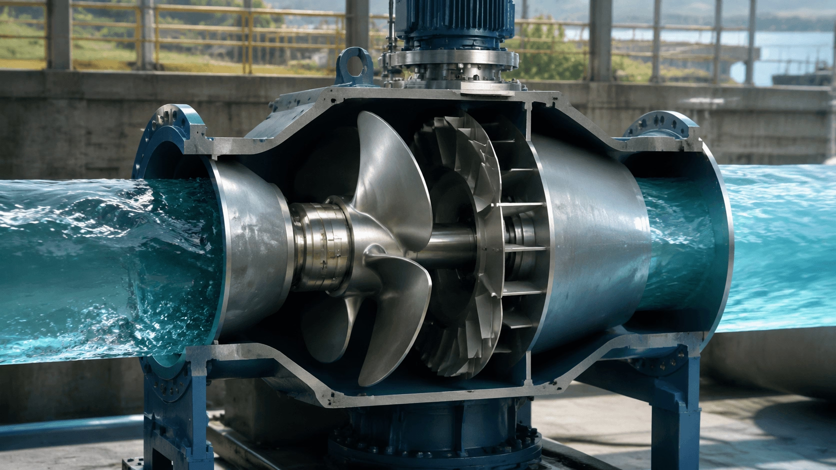
A beginner-friendly technical guide explaining axial flow pump principles, propeller hydraulics, essential formulas, efficiency characteristics, NPSH advantages, real-world applications, and systematic selection methodology.
Table of Contents
- What Is an Axial Flow Pump?
- Why Choose an Axial Flow Pump?
- Operating Principle & Anatomy
- Essential Hydraulic Formulas
- Pump Configurations
- Real-World Applications
- Performance Curve Characteristics
- Selection Decision Matrix
- Material Selection Guide
- Maintenance Schedule for Long Life
- Unit Conversion Reference
- Quick Specification Workflow
- Energy Savings Analysis
- Final Selection Checklist
- Conclusion
1. What Is an Axial Flow Pump?
An axial flow pump is essentially a propeller enclosed within a cylindrical casing. Unlike centrifugal pumps that accelerate fluid radially outward, axial flow pumps push fluid parallel to the pump shaft axis.
The Three Pump Families at a Glance
| Pump Type | Flow Direction | Analogy | Best Application |
|---|---|---|---|
| Centrifugal | 90° outward (radial) | Spinning salad spinner | High pressure, low flow |
| Mixed Flow | ~45° diagonal | Angled fan blade | Medium pressure, medium flow |
| Axial Flow | 0° straight through | Boat propeller in a pipe | Low pressure, massive flow |
2. Why Choose an Axial Flow Pump?
| Metric | Centrifugal | Mixed Flow | Axial Flow |
|---|---|---|---|
| Typical Flow Range | 1–500 m³/h | 100–2,000 m³/h | 500–50,000+ m³/h |
| Typical Head Range | 10–300 m | 5–30 m | 1–15 m |
| Max Efficiency | 70–85% | 82–90% | 80–92% |
| BEP Operating Range | Narrow | Moderate | Very broad |
| NPSH Requirement | Moderate | Low | Very low |
Key Takeaway: If the application requires moving very large volumes of fluid across a low head differential, axial flow pumps are typically the optimal hydraulic solution.
3. Operating Principle & Anatomy
Schematic Overview
┌─────────────────────────────────────┐
│  INLET ──→  [ PROPELLER ]  ──→ OUTLET │
│           (Impeller/Rotor)            │
│                                       │
│      Guide Vanes (Stationary)         │
│      ↓ Straighten swirling flow       │
│                                       │
│        Diffuser Section               │
│      ↓ Convert velocity → pressure    │
└─────────────────────────────────────┘
The Four-Stage Operating Cycle
| Step | Process | Physical Description |
|---|---|---|
| 1. Suction | Water enters the inlet eye | Low pressure region draws fluid axially into the impeller |
| 2. Propulsion | Impeller blades rotate | Blades impart kinetic energy, "screwing" fluid forward |
| 3. Straightening | Guide vanes redirect flow | Stationary vanes remove tangential swirl, restoring axial flow |
| 4. Discharge | Fluid exits at higher pressure | Diffuser section converts remaining velocity head to static pressure |
4. Essential Hydraulic Formulas
All formulas below are presented in plain-text format for universal compatibility.
4.1 Flow Rate (Q)
The volumetric flow rate through the pump annulus:
Q = A * v = (pi * D^2 / 4) * v
Where:
- Q = Flow rate (m³/s or m³/h)
- A = Cross-sectional area of flow passage (m²)
- D = Pipe or impeller diameter (m)
- v = Average axial fluid velocity (m/s)
Worked Example:
An axial flow pump with a 1.2 m diameter impeller and average axial velocity of 3.5 m/s:
Q = (3.1416 * 1.2^2 / 4) * 3.5
Q = 1.131 * 3.5 = 3.96 m³/s
Q = 3.96 * 3600 = 14,256 m³/h
4.2 Euler Pump Equation
The fundamental equation describing energy transfer in turbomachinery:
H = (u2 * vu2 - u1 * vu1) / g
For axial flow pumps where inlet swirl is typically zero (vu1 ≈ 0):
H ≈ (u * vu) / g
Where:
- H = Theoretical head (m)
- u = Blade tip speed, u = pi * D * n / 60 (m/s)
- vu = Tangential component of absolute velocity at outlet (m/s)
- g = Gravitational acceleration (9.81 m/s²)
4.3 Blade Tip Speed
u = (pi * D * n) / 60
Where:
- u = Blade tip speed (m/s); typical range 15–35 m/s
- D = Impeller diameter (m); typical range 0.5–4.0 m
- n = Rotational speed (RPM); typical range 300–1,800 RPM
Cavitation Warning: If tip speed exceeds approximately 35–40 m/s, cavitation risk increases dramatically. This is why large-diameter axial pumps operate at relatively low rotational speeds.
4.4 Specific Speed (Ns)
Ns = (n * sqrt(Q)) / H^0.75
Where (metric units):
- n = Rotational speed (RPM)
- Q = Flow rate at BEP (m³/s)
- H = Head per stage at BEP (m)
| Ns Range | Classification | Impeller Geometry |
|---|---|---|
| < 2,000 | Low specific speed | Radial (centrifugal) |
| 2,000 – 5,000 | Medium specific speed | Mixed flow |
| 5,000 – 15,000+ | High specific speed | Axial flow |
Axial flow pumps typically exhibit Ns > 8,000, confirming their identity as high-flow, low-head machines.
4.5 Axial Thrust Force
Axial flow pumps generate significant axial thrust that must be managed by bearings or hydraulic balancing systems:
F_thrust = rho * g * H * A_hub
Where:
- F_thrust = Axial thrust force (N)
- rho = Fluid density (kg/m³; 1,000 for water)
- H = Pump head (m)
- A_hub = Cross-sectional area of impeller hub (m²)
4.6 Net Positive Suction Head (NPSH)
NPSHa = ((P_atm - P_v) / (rho * g)) + H_s - H_f_s
Where:
- NPSHa = Available NPSH (m); must exceed NPSHr
- P_atm = Atmospheric pressure (~101,325 Pa at sea level)
- P_v = Vapor pressure of water (~2,340 Pa at 20°C)
- H_s = Static suction head (m; positive if flooded, negative if lift)
- H_f_s = Suction line friction losses (m; typically 0.1–1.0 m)
Design Advantage: Axial flow pumps have very low NPSH requirements—often just 1–3 meters—making them ideal for low-water-level intakes, sumps with minimal submergence, and applications where flooded suction cannot be guaranteed.
4.7 Pump Efficiency & Shaft Power
eta (%) = (rho * g * Q * H) / P_shaft * 100

P_shaft (kW) = (rho * g * Q * H) / (eta * 3600)
Efficiency Impact Example:
| Scenario | Parameters | Shaft Power |
|---|---|---|
| High-efficiency pump | Q=10,000 m³/h, H=6 m, eta=88% | ~186 kW |
| Lower-efficiency pump | Q=10,000 m³/h, H=6 m, eta=75% | ~218 kW |
| Power difference | — | 32 kW saved |
At 0.10/kWh over 8,000 operating hours/year, this represents **25,600 in annual energy savings**.
5. Pump Configurations
| Type | Description | Best Application |
|---|---|---|
| Vertical Axial Flow | Motor mounted above, pump below | Deep sumps, wells, cooling towers |
| Horizontal Axial Flow | Shaft oriented horizontally | Pipeline installations, land-based stations |
| Submersible Axial Flow | Motor and pump both submerged | Flood control, drainage, dewatering |
| Tubular Axial Flow | Straight-through pipe design | Lowest hydraulic losses, highest efficiency |
| Adjustable Blade | Blade pitch adjustable during operation | Variable flow requirements without VFD |
6. Real-World Applications
| Industry | Application | Typical Specs | Why Axial Flow? |
|---|---|---|---|
| Flood Control | Stormwater pumping stations | 5,000–30,000 m³/h, 3–8 m head | Massive volume at low head |
| Agriculture | Large-scale irrigation | 1,000–10,000 m³/h, 2–6 m head | High flow, energy efficient |
| Power Plants | Cooling water circulation | 10,000–50,000 m³/h, 5–12 m head | Continuous duty, high reliability |
| Drainage | Land reclamation, polder systems | 2,000–15,000 m³/h, 1–5 m head | Low head, high capacity |
| Aquaculture | Pond/tank water exchange | 500–3,000 m³/h, 1–3 m head | Gentle flow, fish-friendly |
| Shipbuilding | Ballast & bilge pumping | 200–2,000 m³/h, 5–15 m head | Compact footprint, high flow |
| Municipal Water | Raw water intake | 5,000–20,000 m³/h, 3–10 m head | Low NPSH requirement, reliable |
| Chemical Industry | Process fluid circulation | 1,000–5,000 m³/h, 2–8 m head | Corrosion-resistant materials available |
7. Performance Curve Characteristics
Axial flow pumps exhibit a distinctive H-Q curve shape characterized by a rising head toward shut-off:
Head (m)
   │
15 ┤    ╭────╮
12 ┤   ╭╯    ╰──
10 ┤  ╭╯        ← Shut-off head (Q = 0)
 8 ┤ ╭╯
 6 ┤╭╯           ← Normal operating range
 4 ┤╯
 2 ┤
 0 ┼────┬────┬────┬────┬────→ Flow (m³/h)
    0   5K   10K  15K  20K
⚠️ Critical Operational Warning: Axial flow pumps have a rising power curve toward shut-off. Head and power consumption both increase as flow decreases near zero. Never operate at very low flow rates. This causes severe vibration, overheating, and rapid bearing/seal failure. Minimum recommended flow is typically 50–70% of BEP flow.
8. Selection Decision Matrix
| System Requirement | Recommended Pump Type |
|---|---|
| Head > 30 m | Centrifugal |
| Head 10–30 m, Flow 100–2,000 m³/h | Mixed Flow |
| Head 1–15 m, Flow > 500 m³/h | Axial Flow |
| Flow > 5,000 m³/h regardless of head | Axial Flow |
| Suction lift required (> 3 m) | Self-priming Centrifugal |
| NPSHa < 2 m | Axial Flow |
| Variable flow at fixed speed | Adjustable-blade Axial |
Common Myths vs. Reality
| Myth | Technical Reality |
|---|---|
| "They can't generate any pressure" | They generate 1–15 m head—optimal for their design envelope |
| "They're just big fans" | They are precision turbomachines with tight clearances and hydrodynamic blade profiles |
| "They cavitate easily" | They actually have lower NPSH requirements than most centrifugal pumps |
| "Maintenance is complicated" | Fewer wearing parts than centrifugal pumps; maintenance focuses on bearings and seals |
| "Only suitable for clean water" | They handle chemicals, sewage, and slurries when constructed with appropriate materials |
9. Material Selection Guide
| Fluid Type | Recommended Materials | Engineering Notes |
|---|---|---|
| Clean water | Cast iron, carbon steel | Standard, cost-effective |
| Seawater | Bronze, SS 316, duplex stainless | Corrosion and biofouling resistance |
| Sewage / wastewater | Epoxy-coated cast iron, SS | Combined abrasion and corrosion protection |
| Chemicals | Hastelloy, titanium, FRP lining | Match material to specific chemical compatibility |
| Abrasive slurries | High-chrome iron, rubber-lined | Hard-facing on impeller leading edges |
| Food / pharmaceutical | SS 304/316, FDA-compliant elastomers | Sanitary construction, polished surfaces |
10. Maintenance Schedule for Long Life
| Component | Check Interval | Inspection Criteria |
|---|---|---|
| Bearings | Weekly | Temperature < 70°C; vibration within ISO 10816 limits |
| Mechanical Seal | Weekly | Leakage rate acceptable; seal face condition visual check |
| Impeller Clearance | Monthly | Wear ring gap < 0.5% of impeller diameter |
| Vibration Analysis | Monthly | Trend data against baseline; ISO 10816 compliance |
| Shaft Alignment | Quarterly | Runout < 0.05 mm TIR |
| Impeller Condition | Semi-annually | Erosion, corrosion, debris damage inspection |
| Motor Insulation | Annually | Megger test > 1 MΩ |
| Full Overhaul | Every 3–5 years | Replace bearings, seals, wear rings; verify alignment and performance curve |
11. Unit Conversion Reference
| From | To | Multiply By |
|---|---|---|
| m³/h | L/s | 0.2778 |
| m³/s | m³/h | 3,600 |
| GPM (US) | m³/h | 0.2271 |
| Feet | Meters | 0.3048 |
| Inches | Millimeters | 25.4 |
| PSI | m head (water) | 0.7031 |
| Bar | m head (water) | 10.197 |
| kW | HP (metric) | 1.3596 |
| kW | HP (imperial) | 1.3410 |
12. Quick Specification Workflow
Step 1: Define Operating Parameters
| Parameter | Value | Source |
|---|---|---|
| Flow Rate (Q) | ___ m³/h | System demand calculation |
| Total Head (H) | ___ m | Static lift + friction + outlet pressure |
| Fluid Type | ___ | Water, sewage, chemical, slurry |
| Temperature | ___ °C | Affects material selection and NPSH |
| Solids Content | ___ % | Determines impeller type and clearance |
Step 2: Calculate Specific Speed
Compute Ns using the formula in Section 4.4. If Ns > 5,000, axial flow is likely the optimal choice.
Step 3: Verify NPSH Margin
Ensure NPSHa > NPSHr + 0.5 m safety margin at all anticipated operating conditions.
Step 4: Select Materials
Match construction materials to fluid properties using the guide in Section 9.
Step 5: Request and Verify Performance Curves
Obtain from supplier:
- Q-H curve (flow vs. head)
- Efficiency curve
- NPSHr curve
- Power curve
Confirm that the design operating point falls within 70–120% of BEP flow.
13. Energy Savings Analysis
| Pump Type | Efficiency @ 10,000 m³/h, 5 m Head | Annual Energy Cost* |
|---|---|---|
| Legacy centrifugal | 65% | ~$31,400 |
| Modern centrifugal | 78% | ~$26,200 |
| Mixed flow | 85% | ~$24,000 |
| Axial flow | 90% | ~$22,700 |
*Assumptions: 8,000 operating hours/year, electricity at $0.10/kWh
Bottom Line: Selecting an axial flow pump for an appropriate high-flow, low-head application can yield 3,000–8,700/year in energy savings compared to alternative pump types.
14. Final Selection Checklist
| Question | If Yes → |
|---|---|
| Do you need > 500 m³/h flow? | ✅ Strong candidate for axial flow |
| Is total head < 15 m? | ✅ Optimal hydraulic envelope |
| Is NPSHa < 3 m? | ✅ Axial flow excels in low-NPSH conditions |
| Will the pump run > 4,000 hrs/year? | ✅ Efficiency savings justify capital investment |
| Is the fluid relatively free of large solids? | ✅ Standard axial design is suitable |
| Is vertical installation space available? | ✅ Vertical axial configuration is ideal |
Conclusion
Axial flow pumps are the definitive solution for high-volume, low-head fluid handling. While they do not serve high-pressure applications, no other pump type matches their combination of massive flow capacity, high hydraulic efficiency, and low NPSH requirements in the 1–15 m head range.
The Golden Rule of Axial Flow Selection:
Low Head + High Flow = Think Axial Flow
Successful specification requires accurate definition of flow and head parameters, verification of specific speed, confirmation of NPSH margins, and adherence to the minimum-flow operational limits unique to this pump family. When these engineering fundamentals are respected, axial flow pumps deliver decades of reliable, energy-efficient service across flood control, irrigation, power generation, municipal water, and industrial circulation applications.