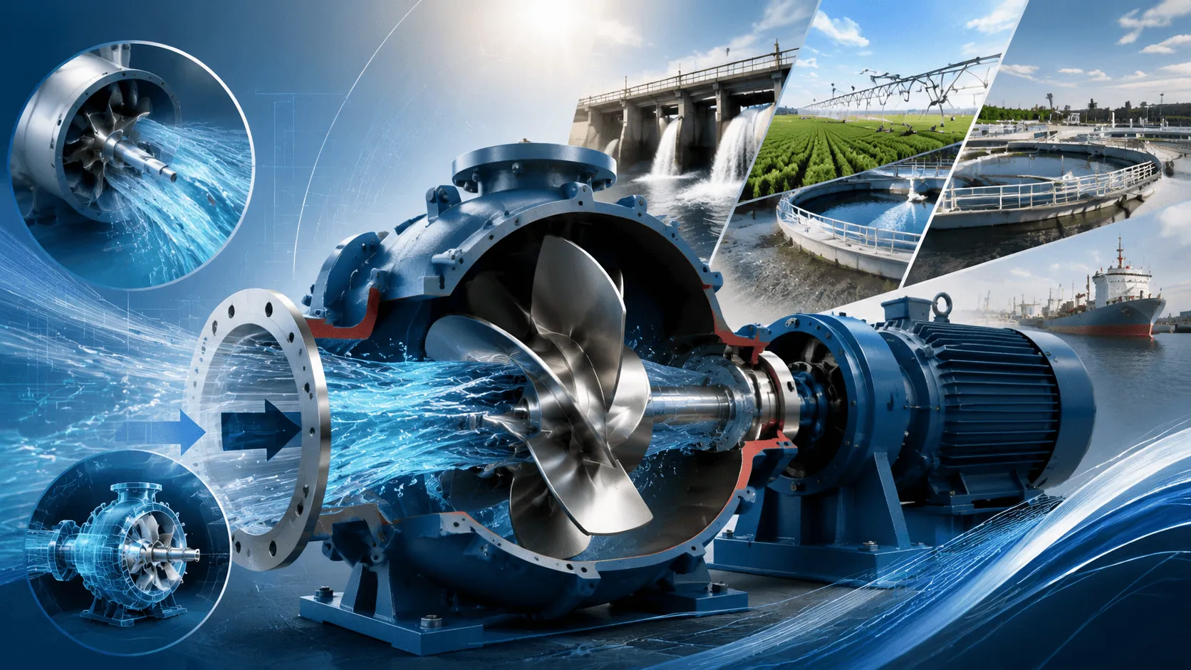
Understanding How Axial Flow Pumps Move Massive Volumes — No Engineering Background Needed
What Is an Axial Flow Pump? (In Plain English)
An axial flow pump is essentially a propeller inside a pipe. Instead of spinning water outward like a centrifugal pump, it pushes water straight through — in the same direction as the pump shaft.
Imagine a boat propeller enclosed in a tube. When it spins, water rushes straight through that tube at high speed. That is an axial flow pump in a nutshell.
The Three Pump "Families" at a Glance
| Pump Type | Flow Direction | Analogy | Best For |
|---|---|---|---|
| Centrifugal | 90° outward (radial) | Spinning salad spinner | High pressure, low flow |
| Mixed Flow | ~45° diagonal | Angled fan blade | Medium pressure, medium flow |
| Axial Flow | 0° straight through | Boat propeller in a pipe | Low pressure, massive flow |
Why Choose an Axial Flow Pump? The Big Advantage
| Metric | Centrifugal | Mixed Flow | Axial Flow |
|---|---|---|---|
| Typical Flow Range | 1–500 m³/h | 100–2,000 m³/h | 500–50,000+ m³/h |
| Typical Head Range | 10–300 m | 5–30 m | 1–15 m |
| Max Efficiency | 70–85% | 82–90% | 80–92% |
| Best Efficiency Point | Narrow | Moderate | Very broad |
| NPSH Requirement | Moderate | Low | Very low |
Key Takeaway: If you need to move a LOT of water through a LOW height difference, axial flow pumps are unbeatable.
How Does It Actually Work? (Step by Step)
The Anatomy of an Axial Flow Pump
┌───────────────────────────────────────────────┐
│  INLET ──→  [ PROPELLER ] ──→  OUTLET         │
│             (Impeller/Rotor)                  │
│                                               │
│    Guide Vanes (Stationary)                   │
│    ↓ Straighten swirling flow                 │
│                                               │
│    Diffuser Section                           │
│    ↓ Convert velocity → pressure              │
└───────────────────────────────────────────────┘
What Happens Inside (4 Simple Steps)
| Step | What Happens | Physics in Plain English |
|---|---|---|
| 1. Suction | Water enters the inlet eye | Low pressure pulls water in |
| 2. Propulsion | Impeller blades spin | Blades "screw" water forward like a propeller |
| 3. Straightening | Guide vanes redirect flow | Remove swirl, make flow go straight |
| 4. Discharge | Water exits at higher pressure | Speed becomes pressure in the diffuser |
The Math Made Simple: Essential Formulas
1. Flow Rate (Q)
The volume of fluid passing through per unit time:
Q = A × v = (π × D² / 4) × v
| Symbol | Meaning | Typical Units |
|---|---|---|
| Q | Flow rate | m³/s, m³/h, GPM |
| A | Cross-sectional area of pipe | m² |
| D | Pipe/impeller diameter | m |
| v | Average fluid velocity | m/s |
Practical Example:
An axial flow pump with a 1.2-meter diameter impeller running at 3.5 m/s velocity:
Q = (3.1416 × (1.2)² / 4) × 3.5 = (3.1416 × 1.44 / 4) × 3.5 = 1.131 × 3.5 ≈ 3.96 m³/s
Q ≈ 3.96 × 3600 = 14,256 m³/h
That is 14,256 cubic meters per hour — enough to fill an Olympic swimming pool in under 3 hours!
2. The Euler Pump Equation (The Heart of Pump Physics)
This equation explains how a pump adds energy to fluid:
H = (u₂ · v_u2 - u₁ · v_u1) / g
For axial flow pumps (where inlet swirl is typically zero):
H ≈ (u × v_u) / g
| Symbol | Meaning | Unit |
|---|---|---|
| H | Theoretical head | m |
| u | Blade tip speed (u = π × D × n / 60) | m/s |
| v_u | Tangential component of absolute velocity | m/s |
| g | Gravitational acceleration | 9.81 m/s² |
What this means in practice: Higher blade speed = more head. Larger diameter = more flow. Axial pumps maximize diameter while keeping head low.
3. Blade Tip Speed (Critical for Design)
u = (π × D × n) / 60
| Symbol | Meaning | Example Value |
|---|---|---|
| u | Blade tip speed | 15–35 m/s (typical) |
| D | Impeller diameter | 0.5–4.0 m |
| n | Rotational speed | 300–1,800 RPM |
Example: A 2-meter diameter impeller at 500 RPM:
u = (3.1416 × 2.0 × 500) / 60 = 3141.6 / 60 ≈ 52.4 m/s
⚠️ Cavitation Warning: If tip speed exceeds ~35–40 m/s, cavitation risk increases dramatically. This is why large axial pumps run at lower RPMs.
4. Specific Speed for Axial Flow Pumps
N_s = (n × √Q) / H^0.75
| Ns Range | Classification | Typical Shape |
|---|---|---|
| < 2,000 | Low specific speed | Radial (centrifugal) |
| 2,000 – 5,000 | Medium specific speed | Mixed flow |
| 5,000 – 15,000+ | High specific speed | Axial flow |
Axial flow pumps typically have Ns > 8,000, confirming their identity as high-flow, low-head machines.
5. Thrust Force on the Impeller (Why Bearings Matter)
Axial flow pumps generate significant axial thrust — force pushing the impeller along the shaft:
F_thrust = ρ × g × H × A_hub
| Symbol | Meaning | Note |
|---|---|---|
| F_thrust | Axial thrust force | N (Newtons) |
| ρ | Fluid density | 1,000 kg/m³ for water |
| H | Pump head | m |
| A_hub | Cross-sectional area of impeller hub | m² |
This is why axial flow pumps need robust thrust bearings — sometimes with hydraulic balancing systems.
6. Net Positive Suction Head (NPSH)
Prevents cavitation — the #1 killer of pump efficiency:
NPSH_a = (P_atm - P_v) / (ρ × g) + H_s - H_f,s
| Symbol | Meaning | Typical Value |
|---|---|---|
| NPSH_a | Available NPSH | Must be > NPSH_r |
| P_atm | Atmospheric pressure | ~101,325 Pa (at sea level) |
| P_v | Vapor pressure of water | ~2,340 Pa at 20°C |
| H_s | Static suction head | Positive if flooded, negative if lift |
| H_f,s | Suction line friction losses | 0.1–1.0 m typical |
Axial flow pumps have very low NPSH requirements — often just 1–3 meters — making them ideal for low-water-level intakes, sumps with minimal submergence, and applications where flooded suction is not possible.
7. Pump Efficiency & Power
η = (ρ × g × Q × H) / P_shaft × 100%
P_shaft = (ρ × g × Q × H) / η
| Scenario | Calculation | Result |
|---|---|---|
| Q = 10,000 m³/h, H = 6 m, η = 88% | P = (1000 × 9.81 × 10,000 × 6) / (0.88 × 3600) | ~186 kW |
| Same job with 75% efficient pump | P = (1000 × 9.81 × 10,000 × 6) / (0.75 × 3600) | ~218 kW |
→ Efficiency difference = 32 kW saved. At 0.10/kWh running 8,000 hrs/year = 25,600 annual savings.
Axial Flow Pump Configurations
| Type | Description | Best For |
|---|---|---|
| Vertical Axial Flow | Motor on top, pump below | Deep sumps, wells, cooling towers |
| Horizontal Axial Flow | Shaft horizontal | Pipeline installations, land-based |
| Submersible Axial Flow | Motor & pump both submerged | Flood control, drainage, dewatering |
| Tubular Axial Flow | Straight-through pipe design | Lowest losses, highest efficiency |
| Adjustable Blade | Blade angle changes during operation | Variable flow requirements |
Real-World Applications
| Industry | Application | Typical Specs | Why Axial? |
|---|---|---|---|
| Flood Control | Stormwater pumping stations | 5,000–30,000 m³/h, 3–8 m head | Massive volume, low head |
| Agriculture | Large-scale irrigation | 1,000–10,000 m³/h, 2–6 m head | High flow, energy efficient |
| Power Plants | Cooling water circulation | 10,000–50,000 m³/h, 5–12 m head | Continuous duty, reliability |
| Drainage | Land reclamation, polder systems | 2,000–15,000 m³/h, 1–5 m head | Low head, high capacity |
| Aquaculture | Pond/tank water exchange | 500–3,000 m³/h, 1–3 m head | Gentle flow, fish-friendly |
| Shipbuilding | Ballast & bilge pumping | 200–2,000 m³/h, 5–15 m head | Compact, high flow |
| Municipal Water | Raw water intake | 5,000–20,000 m³/h, 3–10 m head | Low NPSH, reliable |
| Chemical Industry | Circulation of process fluids | 1,000–5,000 m³/h, 2–8 m head | Corrosion-resistant materials |
Performance Curve Characteristics
Axial flow pumps have a distinctive curve shape:
Head (m)
   │
15 ┤    ╭────╮
12 ┤   ╭╯    ╰─
10 ┤  ╭╯        ← Shut-off head (flow = 0)
 8 ┤ ╭╯
 6 ┤╭╯           ← Normal operating range
 4 ┤╯
 2 ┤
 0 ┼────┬────┬────┬────┬────→ Flow (m³/h)
    0   5K   10K  15K  20K
⚠️ Critical Warning: Axial flow pumps have a rising curve to shut-off — meaning head actually increases as flow decreases near zero. Never operate at very low flow rates! This causes severe vibration, overheating, and rapid bearing/seal failure. Minimum recommended flow is usually 50–70% of best efficiency point (BEP) flow.
Axial vs. Mixed Flow vs. Centrifugal: Decision Matrix
| Your Requirement | Choose This Pump |
|---|---|
| Head > 30 meters | Centrifugal |
| Head 10–30 meters, Flow 100–2,000 m³/h | Mixed Flow |
| Head 1–15 meters, Flow > 500 m³/h | Axial Flow |
| Flow > 5,000 m³/h regardless of head | Axial Flow |
| Need to lift water (suction lift > 3 m) | Centrifugal |
| Very low NPSH available (< 2 m) | Axial Flow |
| Need variable flow with fixed speed | Adjustable blade axial |
Common Myths About Axial Flow Pumps
| Myth | The Truth |
|---|---|
| "They can't generate any pressure" | ❌ False. They generate 1–15 m head — perfect for their design range. |
| "They're just big fans" | ❌ False. They are precision machines with tight clearances and hydrodynamic profiles. |
| "They cavitate easily" | ❌ False. Actually, they have lower NPSH requirements than most pumps. |
| "Maintenance is complicated" | ❌ False. Fewer parts than centrifugal pumps; often just bearings and seals. |
| "Only for water" | ❌ False. They handle chemicals, sewage, and slurries with proper materials. |
Material Selection Guide
| Fluid Type | Recommended Materials | Notes |
|---|---|---|
| Clean water | Cast iron, carbon steel | Standard, cost-effective |
| Seawater | Bronze, stainless steel 316, duplex | Corrosion resistance |
| Sewage/wastewater | Cast iron + epoxy coating, stainless steel | Abrasion + corrosion |
| Chemicals | Hastelloy, titanium, FRP lining | Match to chemical compatibility |
| Abrasive slurries | High-chrome iron, rubber-lined | Hard-facing on impeller |
| Food/pharma | Stainless steel 304/316, FDA-compliant | Sanitary requirements |
Maintenance Schedule for Long Life
| Component | Check Interval | What to Look For |
|---|---|---|
| Bearings | Weekly | Temperature < 70°C, vibration levels |
| Mechanical Seal | Weekly | Leakage rate, seal face condition |
| Impeller Clearance | Monthly | Wear ring gap (should be < 0.5% of diameter) |
| Vibration Analysis | Monthly | ISO 10816 standards compliance |
| Alignment | Quarterly | Shaft runout < 0.05 mm |
| Impeller Condition | Semi-annually | Erosion, corrosion, debris damage |
| Motor Insulation | Annually | Megger test > 1 MΩ |
| Full Overhaul | Every 3–5 years | Bearings, seals, wear rings, alignment |
Quick Unit Conversion Cheat Sheet
| From | To | Multiply By |
|---|---|---|
| m³/h | L/s | × 0.2778 |
| m³/s | m³/h | × 3,600 |
| GPM (US) | m³/h | × 0.2271 |
| Feet | Meters | × 0.3048 |
| Inches | Millimeters | × 25.4 |
| PSI | m head (water) | × 0.7031 |
| Bar | m head (water) | × 10.197 |
| kW | HP (metric) | × 1.3596 |
| kW | HP (imperial) | × 1.3410 |
How to Specify an Axial Flow Pump (5-Minute Guide)
Step 1: Define Your Numbers
| Parameter | Your Value | How to Get It |
|---|---|---|
| Flow Rate (Q) | ___ m³/h | Calculate system demand |
| Total Head (H) | ___ m | Static lift + friction + outlet pressure |
| Fluid Type | ___ | Water, sewage, chemical? |
| Temperature | ___ °C | Affects material & NPSH |
| Solids Content | ___ % | Determines impeller design |
Step 2: Calculate Specific Speed
Use the formula above. If Ns > 5,000, axial flow is likely your best choice.
Step 3: Check NPSH
Ensure NPSH_a (available) > NPSH_r (required by pump) + 0.5 m safety margin.
Step 4: Select Material
Match to fluid properties (see material table above).
Step 5: Request Curves
Ask your supplier for:
- Q-H curve (flow vs. head)
- Efficiency curve
- NPSH required curve
- Power curve
Verify your operating point is within 70–120% of BEP flow.
Energy Savings: The Numbers Don't Lie
| Pump Type | Efficiency at 10,000 m³/h, 5m Head | Annual Energy Cost* |
|---|---|---|
| Old centrifugal (65% eff) | 65% | ~$31,400 |
| Modern centrifugal (78% eff) | 78% | ~$26,200 |
| Mixed flow (85% eff) | 85% | ~$24,000 |
| Axial flow (90% eff) | 90% | ~$22,700 |
*Assumptions: 8,000 operating hours/year, electricity at $0.10/kWh
→ Switching to an axial flow pump for the right application saves 3,000–8,700/year in energy alone.
Final Checklist: Is an Axial Flow Pump Right for You?
| Question | If Yes → |
|---|---|
| Do you need > 500 m³/h flow? | ✅ Consider axial flow |
| Is your total head < 15 meters? | ✅ Strong candidate |
| Is your NPSH available < 3 meters? | ✅ Axial flow excels here |
| Will the pump run > 4,000 hrs/year? | ✅ Efficiency savings justify investment |
| Is your fluid relatively clean (no large solids)? | ✅ Standard design works |
| Do you have vertical space for installation? | ✅ Vertical axial is ideal |
Conclusion
Axial flow pumps are the unsung heroes of high-volume fluid handling. They do not get the glory of high-pressure pumps, but when you need to move massive amounts of water efficiently across low head differences, nothing else comes close.
Remember the golden rule:
Low head + High flow = Think Axial Flow
Ready to find your pump? Gather your Q (flow) and H (head) numbers, and let us match you with the perfect axial flow pump for your application.
Need help with pump selection? Our engineering team can analyze your system requirements and recommend the optimal axial flow pump configuration — vertical, horizontal, submersible, or tubular.