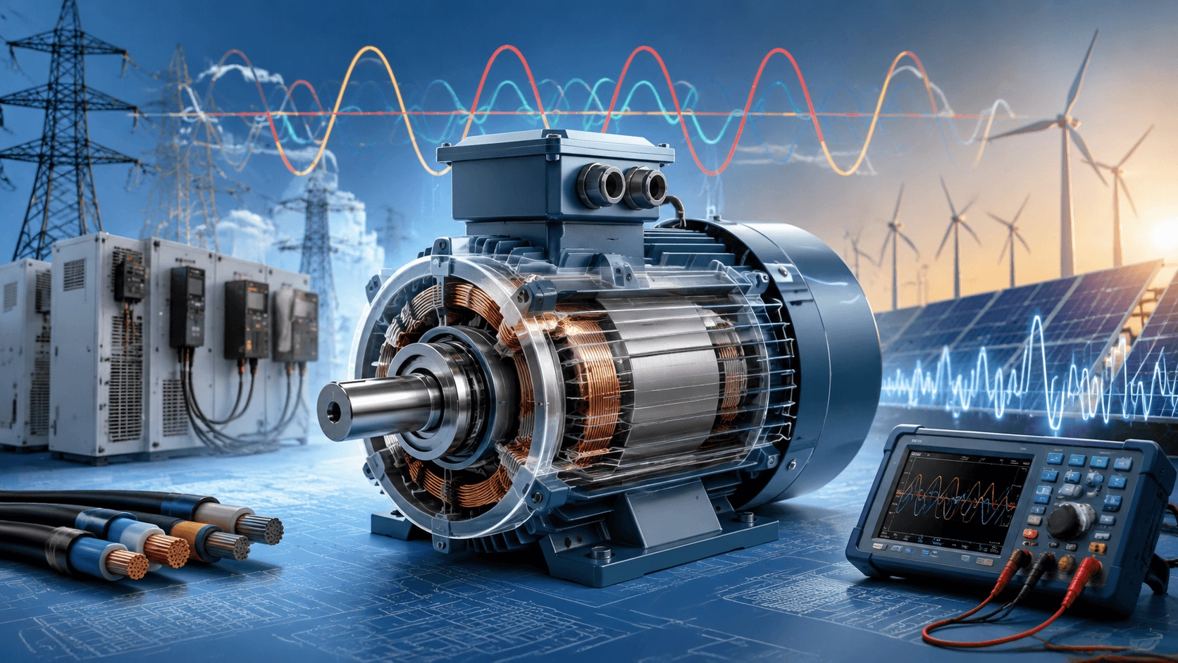
2026 AC Motor Voltage Guide: Rated vs. nominal voltage distinctions, line/phase vector relationships, IEC/NEMA utilization standards (230/400V, 460V/480V), the physics of voltage deviations (under/over/unbalance), NEMA derating curves, dV/dt reflected wave phenomena, scientific selection methodologies, and advanced optimization (SiC VFDs, sine-wave filters, DVRs) – compiled with TECHO engineering expertise.
Introduction: Voltage as the Lifeblood of Electromechanical Conversion
Voltage is the fundamental electromotive force that drives current through motor windings, establishes the critical magnetic flux in the air gap, and ultimately dictates the torque-producing capability of an alternating current (AC) motor. Unlike power or speed, which can be dynamically adjusted via mechanical or electronic means, voltage is a non-negotiable boundary condition. A mismatch between a motor’s dielectric design and the supply voltage leads to immediate, irreversible consequences: insulation breakdown, catastrophic thermal runaway, or severe efficiency degradation.
In the industrial landscape of 2026, the proliferation of distributed energy resources (DERs), solar/wind microgrids, and fast-switching Silicon Carbide (SiC) Variable Frequency Drives (VFDs) has fundamentally altered power quality. Voltage flicker, high-frequency harmonics, and steep voltage transient spikes (dV/dt) are now commonplace. This guide delivers a rigorous, engineering-focused analysis of AC motor voltage, demystifying complex vector relationships, international tolerance standards, and the hidden physics of voltage-induced failures. It is an essential manual for electrical engineers, plant managers, and reliability specialists seeking to bulletproof their electromechanical systems.
Core Definitions: Understanding AC Motor Voltage Fundamentals
AC motor voltage is not a single scalar value; it is a multi-dimensional matrix of standardized ratings, vector measurements, and dielectric limits. Confusion between these terms is the root cause of over 80% of voltage-related commissioning failures.
1. Rated Voltage (V_n): The Dielectric and Magnetic Design Baseline
The rated voltage (V_n) is the specific RMS (Root Mean Square) AC voltage the motor’s magnetic circuit and insulation system are engineered to handle continuously. According to IEC 60034-1, a motor must be capable of delivering its rated power continuously at a voltage deviation of ±5% from V_n, and must operate (though not necessarily at rated power) without thermal damage at a deviation of ±10%.
Engineering Note: The insulation system (e.g., Class F at 155°C, Class H at 180°C) is tested against the peak voltage stress, not just the RMS value. For inverter-fed motors, IEC 60034-18-41 mandates enhanced dielectric strength to withstand repetitive voltage spikes.
2. Line Voltage (V_line): The Supply System Potential
Line voltage (or line-to-line voltage) is the electrical potential measured between any two phase conductors in a three-phase system. It is the primary parameter used for system matching. When evaluating VFD outputs or long cable runs, engineers must also consider the Peak Line Voltage, which can be significantly higher than the RMS value due to switching transients and reflected wave phenomena.
3. Phase Voltage (V_phase): The Winding Stress Metric
Phase voltage is the actual potential difference applied across a single individual stator coil/winding. The relationship between line and phase voltage is strictly governed by the internal or external winding topology (Star/Y or Delta/Δ). Misunderstanding this relationship during Star-Delta starting or dual-voltage wiring is a leading cause of immediate motor burnout.
Line vs. Phase Voltage Vector Mathematics (Three-Phase Systems)
Because three-phase voltages are shifted by 120 electrical degrees, they do not add arithmetically; they add vectorially.
-
Star (Y) Connection:
V_line = √3 × V_phase
I_line = I_phase
Application: Used for high-voltage systems and Star-Delta soft starting. In Star, the winding sees only 57.7% (1/√3) of the line voltage. -
Delta (Δ) Connection:
V_line = V_phase
I_line = √3 × I_phase
Application: Used for high-torque, low-voltage applications and standard direct-on-line (DOL) starting.
⚠️ Critical Wiring Warning:
If a motor nameplate reads230/400V Δ/Y, it means the individual windings are rated for exactly 230V.
- On a 400V supply, you MUST wire it in Star (Y) (400 ÷ √3 ≈ 230V per winding).
- On a 230V supply, you MUST wire it in Delta (Δ) (230V per winding).
Wiring this motor in Delta on a 400V supply applies 400V to a 230V winding (a 74% over-voltage), resulting in instantaneous magnetic saturation, massive current spikes, and catastrophic failure within seconds.
4. Nominal vs. Utilization Voltage: The 5% Rule
A common source of confusion is the difference between system nominal voltage and equipment utilization voltage.
- Nominal Voltage refers to the utility transformer output (e.g., 480V in North America, 400V in Europe).
- Utilization Voltage (the motor's V_n) is intentionally rated lower (e.g., 460V in North America, 380V/400V in Europe) to account for the standard 5% voltage drop that occurs across facility distribution cables and switchgear under full load.
International Standard AC Motor Voltage Ratings (2026 Matrix)
Global supply architectures are dictated by regional grid histories. IEC and NEMA standards define the acceptable utilization voltages to ensure interoperability.
1. IEC Standard Voltage Ratings (Global 50Hz / 60Hz Harmonized)
IEC 60034 governs motors in Europe, Asia, Africa, and increasingly, globalized OEM equipment. The 690V standard has become dominant in 2026 for heavy industry (110kW to 1000kW) to avoid the massive cost of medium-voltage (MV) switchgear and cabling.
| IEC Rated Voltage (V) | Winding Topology | Phase Voltage (V) | Primary Application & Region | Power Range |
|---|---|---|---|---|
| 230 / 400 | Δ / Y | 230 | Standard LV Industrial (Europe, Asia, ME) | 0.12 kW – 90 kW |
| 400 / 690 | Δ / Y | 400 | Heavy LV Industrial / VFD Soft-Start | 90 kW – 1000 kW |
| 690 / 1190 | Δ / Y | 690 | Marine, Wind Turbines, Mining | 500 kW – 3 MW |
| 3000 / 6000 / 11000 | Y (Only) | 1732 / 3464 / 6350 | Medium Voltage (MV) Heavy Industry | 200 kW – 20 MW+ |
2. NEMA Standard Voltage Ratings (North America 60Hz)
NEMA MG 1 strictly defines "Utilization Voltages" to align with NEC (National Electrical Code) transformer taps and feeder drop calculations.
| NEMA Rated Voltage (V) | System Nominal (V) | Application Profile | Typical Power Range |
|---|---|---|---|
| 230 / 460 | 240 / 480 | Standard Commercial & Industrial | 0.5 HP – 500 HP |
| 575 | 600 | Canadian Industrial / Heavy Mining | 100 HP – 1500 HP |
| 2300 / 4160 / 6600 | 2400 / 4160 / 6900 | Medium Voltage (MV) Pumps & Compressors | 500 HP – 10,000 HP |
3. The 2026 Dual-Rated / Multi-Frequency Paradigm
Modern global OEMs utilize 9-lead or 12-lead dual-rated motors (e.g., 230/400V 50Hz // 265/460V 60Hz). This is achieved by designing the magnetic core to maintain a constant Volts-per-Hertz (V/Hz) ratio.
- At 50Hz: 400V ÷ 50Hz = 8.0 V/Hz
- At 60Hz: 460V ÷ 60Hz = 7.66 V/Hz (Slightly lower flux density, preventing saturation at the higher frequency).
AC Motor Voltage Types: Single-Phase vs. Three-Phase Architectures
1. Single-Phase AC Motors (1φ)
Single-phase power produces a pulsating magnetic field, not a rotating one. Therefore, these motors require auxiliary starting mechanisms (capacitors, centrifugal switches, or shaded poles) to create a phase shift and initiate rotation.
- Voltage Limits: 115V, 230V (NEMA) / 230V (IEC).
- Power Ceiling: Practically limited to ≤ 5 kW (approx. 5 HP). Beyond this, the starting current and mechanical vibration become unmanageable.
- 2026 Trend: Rapid replacement by ECMs (Electronically Commutated Motors). ECMs accept single-phase AC, rectify it to a DC bus, and internally drive a 3-phase permanent magnet motor via a micro-inverter, achieving IE5 ultra-premium efficiency.
2. Three-Phase AC Motors (3φ)
The 120° phase displacement inherently generates a smooth, constant-magnitude Rotating Magnetic Field (RMF).
- Advantages: Self-starting, high power density, zero torque pulsation, and superior efficiency (IE3 to IE5).
- Voltage Range: 200V to 13,800V.
- Dominance: Mandated for all continuous industrial processes, heavy HVAC, and high-inertia loads.
The Physics of Failure: How Voltage Deviations Destroy Motors
AC motors are highly sensitive to voltage quality. The relationship between voltage, magnetic flux, and torque is non-linear. Deviations trigger cascading thermodynamic and electromagnetic failures.
1. Under-Voltage (The Torque Collapse)
When supply voltage drops, the magnetic flux in the air gap weakens. Because motor torque is proportional to the square of the voltage, the performance degradation is exponential.
The Torque-Voltage Square Law:
T_actual = T_rated × (V_actual ÷ V_rated)²
Example: A 10% under-voltage condition (V_actual = 0.90 × V_rated) results in:
T_actual = T_rated × (0.90)² = 0.81 × T_rated
Result: A 19% loss in torque. To maintain the same mechanical load, the motor slip must increase drastically, drawing excessive stator current (I²R copper losses), leading to rapid thermal destruction of the windings.
2. Over-Voltage (Magnetic Saturation & Core Heating)
Over-voltage forces the motor’s silicon-steel laminations past their linear magnetic region into saturation (the knee of the B-H curve).
- Consequence: The core cannot absorb additional magnetic flux. The excess voltage drives a massive, non-linear spike in magnetizing current (reactive current).
- Damage: This causes severe hysteresis and eddy current losses (iron losses) in the core, generating intense internal heat that bakes the winding insulation from the inside out, while simultaneously destroying the power factor.
3. Three-Phase Voltage Unbalance (The Silent Killer)
Voltage unbalance occurs when the three line voltages are not perfectly equal. According to the theory of Symmetrical Components, an unbalanced voltage system creates a "Negative Sequence" voltage component. This negative sequence generates a magnetic field that rotates in the opposite direction of the rotor.
- The Multiplier Effect: A mere 2% voltage unbalance can induce a 15% to 20% current unbalance.
- Thermal Impact: The reverse-rotating field induces double-frequency (100Hz/120Hz) currents in the rotor bars and stator windings, creating severe localized hotspots that surface temperature sensors cannot detect until the insulation carbonizes and fails.
NEMA MG 1 Derating Rule for Unbalance:
If voltage unbalance exceeds 1%, the motor MUST be derated to prevent thermal failure.
- 2% Unbalance = Derate to ~90% of nameplate HP/kW.
- 3% Unbalance = Derate to ~80% of nameplate HP/kW.
- 5% Unbalance = Derate to ~75% of nameplate HP/kW (Operation above 5% is strictly prohibited by IEC/NEMA).
Voltage Unbalance Calculation Formula (NEMA Standard):
- Measure all three line voltages: V12, V23, V31.
- Calculate Average Voltage:
V_avg = (V12 + V23 + V31) ÷ 3 - Find Maximum Deviation:
Max_Dev = Maximum of |V12 - V_avg|, |V23 - V_avg|, |V31 - V_avg| - Calculate Percentage:
Unbalance (%) = (Max_Dev ÷ V_avg) × 100%
AC Motor Voltage Selection: Common Mistakes & Scientific Method
The 6 Most Catastrophic Voltage Selection Mistakes
- Mistake 1: Ignoring the "Utilization vs. Nominal" Gap. Specifying a 480V motor for a 480V transformer bus. Under full load, the bus will drop to 456V, causing severe under-voltage operation. Correction: Always specify 460V motors for 480V systems.
- Mistake 2: Neglecting Long-Feeder Voltage Drop. Failing to calculate I²R voltage drop for motors located >50 meters from the MCC (Motor Control Center).
- Mistake 3: Star-Delta Wiring Errors. Manually wiring a 400V Delta motor in Star on a 400V grid, applying only 230V to the windings, resulting in a 67% torque loss and immediate stalling under load.
- Mistake 4: Blindly Trusting VFD Output Voltage. Assuming a VFD outputs pure sine-wave voltage. Fast-switching IGBTs and SiC transistors create steep dV/dt wavefronts. If the cable is long, reflected wave phenomena can cause voltage doubling at the motor terminals (e.g., 650V DC bus × 2 = 1300V peak spike), instantly puncturing standard insulation.
- Mistake 5: Overlooking Harmonic Voltage Distortion (THDv). Non-linear loads (LEDs, UPS, rectifiers) distort the voltage sine wave. High THDv causes stray load losses and severe overheating, even if the RMS voltage reads perfectly.
- Mistake 6: Single-Phase Sizing for High-Inertia Loads. Using 230V single-phase capacitor-start motors for heavy compressors, leading to centrifugal switch failure and start-winding burnout due to prolonged acceleration times.
Step-by-Step Scientific Voltage Selection Method (IEC/NEMA Aligned)
Step 1: Profile the True Supply Architecture
Measure the actual no-load and full-load RMS voltages at the Point of Common Coupling (PCC). Calculate the baseline voltage unbalance and THDv. Ensure unbalance is ≤ 1% and THDv is ≤ 5% (per IEEE 519 / IEC 61000-2-2).
Step 2: Execute Rigorous Voltage Drop Calculations
For every cable run, calculate the voltage drop. IEC 60364 and NEC mandate a maximum combined drop of 3% for feeders and 5% total from transformer to motor terminals.
- Three-Phase Drop Formula:
V_drop = (√3 × I × L × R × cosφ) ÷ 1000
(Where I = Full Load Amps, L = One-way length in meters, R = Conductor resistance in Ω/km, cosφ = Power Factor). - Action: If V_drop > 3%, upsize the cable cross-section (mm² / AWG) or install local step-up transformers.
Step 3: Select the Utilization Voltage & Topology
Match the motor V_n to the loaded supply voltage. For systems requiring high starting torque but limited grid capacity, specify a Star-Delta or Part-Winding start motor (e.g., 400/690V Δ/Y) to reduce inrush current to 33%.
Step 4: Specify Inverter-Duty Insulation (If VFD Applied)
If the motor will be fed by a VFD, you MUST specify Inverter-Duty Windings (IEC 60034-18-41 / NEMA MG 1 Part 31). This mandates magnet wire with heavy dielectric varnish capable of withstanding repetitive dV/dt spikes and high peak voltages without partial discharge (corona) inception.
Step 5: Integrate Advanced Protection Relays
Specify smart motor protection relays (e.g., Schneider TeSys, ABB UMC) programmed to trip on:
- Under-voltage (< 90% V_n for > 5 seconds)
- Over-voltage (> 110% V_n)
- Voltage Unbalance (> 2% instantaneous)
- Phase Loss / Phase Reversal
Scenario-Specific Voltage Selection & Engineering Guidelines
1. Industrial Centrifugal Pumps & Fans (Variable Torque)
- Grid Profile: Stable 3-phase, long cable runs to remote pump stations.
- Voltage Selection: 400V / 690V (IEC) or 460V (NEMA).
- 2026 Engineering Mandate: Because these are almost exclusively VFD-driven, specify IE4/IE5 Synchronous Reluctance (SynRM) or PM motors. Install dV/dt chokes or Sine-Wave Filters at the VFD output if the motor cable exceeds 30 meters to eliminate reflected wave voltage spikes and protect the bearings from Electrical Discharge Machining (EDM) currents.
2. Heavy Mining & Cement (High-Inertia Conveyors / Crushers)
- Grid Profile: Weak grids, high voltage dip during starting, severe harmonic distortion.
- Voltage Selection: Medium Voltage (MV) 3300V, 6600V, or 11000V.
- 2026 Engineering Mandate: Use Wound Rotor Induction Motors (WRIM) with liquid rheostat starters, or Active Front End (AFE) VFDs on MV synchronous motors. AFE drives draw unity power factor current and eliminate harmonic voltage distortion on the weak mine grid. Specify IP65 enclosures and Class H insulation to survive conductive dust and thermal stress.
3. Commercial HVAC & Data Center Cooling
- Grid Profile: Strict noise limits, high redundancy requirements, backup generator power.
- Voltage Selection: 400V / 460V 3-phase for chillers/AHUs; 230V 1-phase for small FCUs.
- 2026 Engineering Mandate: Data centers experience massive voltage sags during utility transfers. Specify motors with high Thermal Mass and integrate Dynamic Voltage Restorers (DVRs) on the main bus to inject missing voltage within 2 milliseconds, preventing chiller motor contactors from dropping out during a grid fault.
4. Agricultural Irrigation & Solar Pumping
- Grid Profile: Extremely weak rural grids, massive voltage fluctuations, or off-grid Solar PV arrays.
- Voltage Selection: 400V / 460V 3-phase.
- 2026 Engineering Mandate: For solar applications, use Solar VFDs that accept a wide DC input range (e.g., 300V to 800V DC) directly from PV strings, bypassing the AC grid entirely. For grid-tied rural motors, install Automatic Voltage Regulators (AVRs) and specify wide-tolerance NEMA Design C motors to handle low-voltage starting conditions.
5. Marine & Offshore (Ship Propulsion & Winches)
- Grid Profile: 60Hz shipboard microgrids, 440V or 690V ungrounded Delta systems.
- Voltage Selection: 690V 3-phase (IEC) / 460V (NEMA).
- 2026 Engineering Mandate: Marine systems often use ungrounded Delta to maintain operation during a single line-to-ground fault. Motors must be equipped with Insulated Monitoring Devices (IMDs) and shaft grounding rings to prevent bearing fluting. Specify marine-class space heaters to prevent condensation-induced dielectric failure during standby.
Voltage Optimization & System Compatibility Strategies
Selecting the right motor is only 50% of the equation. Optimizing the electrical environment ensures the motor operates at peak magnetic efficiency and achieves its designed 20-year L10 bearing life.
1. Mitigate dV/dt and Reflected Waves (VFD Applications)
With the 2026 shift toward Silicon Carbide (SiC) VFDs, switching frequencies have increased, creating incredibly steep voltage wavefronts (dV/dt > 10,000 V/μs).
- Solution: Install Sine-Wave Filters (LC filters) at the drive output. These convert the PWM square pulses back into a smooth, pure sinusoidal voltage waveform before it reaches the motor cable, completely eliminating peak voltage overshoot, acoustic motor noise, and capacitive leakage currents.
2. Implement Active Phase Balancing
In facilities with heavy single-phase loading (welders, industrial ovens, lighting), the 3-phase bus becomes unbalanced.
- Solution: Deploy Static Var Generators (SVGs) or Active Power Filters (APFs). Unlike passive capacitor banks, SVGs use power electronics to inject precise reactive and negative-sequence currents, dynamically balancing the 3-phase voltage to within 0.5% in real-time, eliminating motor hotspots.
3. Upgrade to Inverter-Grade Insulation & Bearing Protection
Voltage stress in modern plants is high-frequency, not just RMS.
- Solution: Mandate Corona-Resistant Magnet Wire (using nano-filled enamel) for all VFD-fed motors. Furthermore, install Conductive Micro-Fiber Shaft Grounding Rings (e.g., AEGIS rings) to safely route high-frequency capacitive discharge currents away from the motor bearings, preventing electrical pitting and premature mechanical failure.
4. Deploy Dynamic Voltage Restorers (DVR) for Critical Processes
For semiconductor fabs, pharmaceutical lines, or continuous extruders where a 200ms voltage sag costs millions in scrapped product.
- Solution: Install a DVR in series with the motor feeder. The DVR utilizes ultracapacitors and fast IGBTs to detect a voltage sag and inject the exact missing voltage vector within 1/4 of a cycle, rendering the motor completely immune to upstream grid faults.
5. Routine Power Quality & Thermographic Audits
Voltage degradation is often invisible until failure occurs.
- Solution: Integrate Class A Power Quality Analyzers (per IEC 61000-4-30) into the MCC to log voltage sags, swells, and THD continuously. Pair this with quarterly Infrared Thermography of the motor terminal boxes and stator cores to identify localized heating caused by hidden voltage unbalance or loose, high-resistance terminations.
Key Takeaways: Master AC Motor Voltage for Absolute Reliability
AC motor voltage is the most unforgiving parameter in electromechanical engineering. Unlike speed or power, which can be managed via control loops, voltage dictates the fundamental survival of the motor's magnetic and dielectric systems.
The core lesson of this 2026 guide is that voltage selection extends far beyond matching a nameplate number to a transformer bus. It requires a holistic understanding of utilization vs. nominal voltage, the vector mathematics of Star/Delta topologies, and the severe, exponential penalties of under-voltage (torque collapse) and unbalance (negative-sequence heating).
In the era of SiC drives and renewable microgrids, traditional selection methods are obsolete. Engineers must now account for dV/dt reflected waves, harmonic voltage distortion, and high-frequency bearing currents. By executing the scientific selection method—calculating precise feeder voltage drops, mandating inverter-duty insulation, deploying sine-wave filters, and integrating smart unbalance protection—facilities can eliminate voltage-induced failures, optimize magnetic efficiency, and secure the 20-year operational lifespan of their critical rotating assets.
Master AC Motor Voltage with Professional Engineering Expertise
Voltage mismatch, unbalance, and transient spikes are the leading, yet most preventable, causes of catastrophic AC motor failure. In 2026, these issues cost industrial and commercial operations millions annually in unplanned downtime, scrapped production, and emergency rewinding costs.
Our team of certified electrical power quality and motor engineering experts possesses decades of specialized experience in advanced voltage selection, grid-impact analysis, dV/dt mitigation, and predictive system design. We offer bespoke, data-driven solutions—from comprehensive power quality audits and precise feeder voltage drop modeling to the specification of Active Front End (AFE) drives, sine-wave filtering, and IEC 61850 integrated protection architectures.
Whether you are commissioning a new heavy-industrial plant, retrofitting legacy motors for VFD integration, or troubleshooting recurrent, "unexplained" winding failures, we tailor our engineering services to your unique grid constraints and operational demands.
Request Your Custom AC Motor Voltage & Power Quality Consultation today to bulletproof your electromechanical assets against the complexities of the modern electrical grid.
© 2026 TECHO Engineering Solutions. All rights reserved. This guide is provided for advanced technical reference. All motor selection, power system design, and protection coordination must be validated by a licensed Professional Engineer (PE) or Chartered Engineer (CEng) in strict accordance with local electrical codes, IEC 60034, NEMA MG 1, and IEEE standards.